Article Content
For Substation Metering & Protection: JLS-20K 11kV Cast-Resin Current Transformer per IEC 61869-2
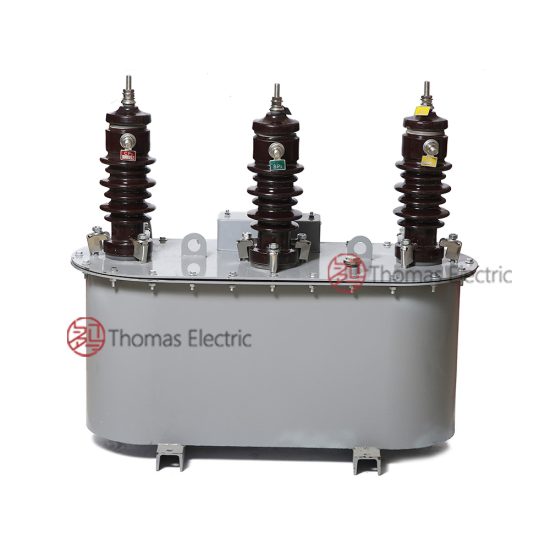
Introduction to the JLS-20K Current Transformer
The JLS-20K is a high-reliability, outdoor-rated cast-resin current transformer (CT) engineered for accurate current measurement and protective relay coordination in 11kV medium-voltage networks—equivalent to the domestic 10kV system voltage used across China and select Asian markets. Designed in strict compliance with IEC 61869-2 and GB/T 20840.2, this instrument transformer provides galvanic isolation between primary conductors carrying up to 11kV and secondary instrumentation circuits operating at safe SELV levels (typically ≤110V). Its solid dielectric construction eliminates fire hazards and environmental risks associated with oil-filled alternatives, making it ideal for urban substations, industrial facilities, and renewable energy interconnection points.
Operating Principle of Cast-Resin Insulation
Cast-resin insulation in the JLS-20K employs vacuum pressure impregnation (VPI) epoxy technology to fully encapsulate the magnetic core and primary winding within a homogeneous, void-free polymer matrix. This process begins with degassing raw epoxy components under vacuum to remove moisture and air, followed by precise mixing and injection into a preheated mold containing the wound core assembly. Curing occurs under controlled thermal profiles (typically 80–120°C over 4–6 hours), resulting in a monolithic structure with dielectric strength exceeding 20 kV/mm. The absence of liquid or gaseous media ensures long-term dimensional stability, resistance to partial discharge (PD < 5 pC at 1.2 × Ur), and immunity to leakage or degradation under thermal cycling. Unlike oil-immersed CTs, which rely on fluid convection for heat dissipation, the JLS-20K’s thermally conductive resin (λ ≈ 0.8 W/m·K) transfers heat radially through the housing, enabling continuous operation at ambient temperatures from –40°C to +40°C without derating.
Advantages Over Oil-Immersed Designs
Compared to traditional oil-filled CTs, the JLS-20K offers significant operational and safety benefits. First, its dry-type construction eliminates flammability risks, satisfying stringent fire codes in indoor switchgear rooms and densely populated areas. Second, maintenance requirements are drastically reduced—no oil sampling, gas analysis, or tank inspections are needed over its 25–30 year design life. Third, the compact footprint (typical height: 380 mm; diameter: 180 mm) enables space-efficient mounting on poles, crossarms, or switchgear busbars. Environmental resilience is another key advantage: the UV-stabilized cycloaliphatic epoxy housing withstands salt fog (IEC 60068-2-11), dust ingress (IP54 rating), and humidity levels up to 95% RH non-condensing. Finally, electromagnetic performance is enhanced by the use of grain-oriented electrical steel (GOES) cores with low hysteresis loss (<0.8 W/kg at 1.5 T, 50 Hz), ensuring accuracy class stability under harmonic distortion and DC offset conditions common in modern grids with power electronics.
Typical Applications Overview
The JLS-20K is deployed across diverse medium-voltage infrastructure where precision, reliability, and minimal lifecycle cost are paramount. In utility-owned 11kV/10kV distribution substations, it supplies metering-grade secondary currents (e.g., 1A or 5A) to revenue-class kWh meters while simultaneously feeding protection-class windings to overcurrent relays (e.g., 5P10 or 5P20). Industrial plants utilize it for motor protection, arc-flash mitigation, and load profiling in 10kV motor control centers. Renewable integration projects—particularly solar farms and wind parks—leverage its wide dynamic range (up to 4000:1 ratio options) to monitor both normal generation output and fault currents during grid disturbances. Rural electrification schemes benefit from its robustness against lightning surges (BIL 75 kV) and ability to operate reliably at altitudes up to 2000 m without performance degradation.
Technical Specifications
The JLS-20K adheres to a rigorous set of electrical, mechanical, and environmental parameters defined by international and national standards. Below is a comprehensive specification table followed by detailed contextual explanations.
| Parameter | Value |
|---|---|
| Rated System Voltage (Ur) | 11 kV (IEC); 10 kV (GB) |
| Primary Current (Ip) | 50 A to 4000 A (standard steps) |
| Secondary Current (Is) | 1 A or 5 A |
| Current Ratio | e.g., 600/5, 1000/1, 2000/5 (customizable) |
| Metering Accuracy Class | 0.2S, 0.5S per IEC 61869-2 |
| Protection Accuracy Class | 5P10, 5P15, 5P20 |
| Rated Output (Burden) | 5 VA to 30 VA (per class) |
| Short-Time Thermal Current | 25 kA for 1 s (Ith) |
| Dynamic Withstand Current | 62.5 kA peak (Idyn) |
| Power Frequency Withstand Voltage | 28 kV rms, 1 min (phase-to-earth) |
| Lightning Impulse Withstand Voltage | 75 kV peak (1.2/50 μs) |
| Insulation Material | VPI cycloaliphatic epoxy resin |
| Core Material | GOES M6 grade, 0.3 mm lamination |
| Ambient Temperature Range | –40°C to +40°C |
| Altitude Limit | ≤2000 m (derating above 1000 m) |
| Ingress Protection | IP54 |
Electrical Performance Parameters
The JLS-20K delivers metrological precision under both steady-state and transient conditions. For metering applications, the 0.2S class guarantees composite error ≤ ±0.2% at 20–120% of rated current and ≤ ±0.5% at 5–20%, critical for revenue metering per IEC 62053-22. Protection windings (e.g., 5P20) maintain ≤5% composite error at 20× rated current with specified burden, ensuring reliable relay operation during high-magnitude faults. The transformer’s knee point voltage (Vk) exceeds 200 V for 5P20 variants, preventing saturation during external faults with significant DC offset. Rated outputs are precisely matched to connected burdens: a 15 VA 5P10 winding assumes a total loop impedance of 0.6 Ω (for 5A secondary), including relay coil, wiring, and contact resistance. Exceeding this burden degrades accuracy and may cause thermal overload during prolonged overcurrent events.
Environmental and Mechanical Ratings
Designed for harsh outdoor environments, the JLS-20K meets IEC 60068 climatic test requirements. The housing features hydrophobic surface properties to shed rainwater and resist tracking under pollution (creepage distance ≥240 mm for 11kV). Mounting brackets accommodate standard M12 bolts with torque specification of 35 N·m, ensuring secure attachment to porcelain insulators or steel structures. Thermal performance is validated per IEC 61869-2 Annex B: temperature rise under 1.2× rated current does not exceed 60 K for windings and 50 K for terminals. At altitudes above 1000 m, the power frequency withstand voltage must be reduced by 1% per 100 m increment; thus, at 2000 m, the test voltage becomes 25.2 kV rms. Humidity resistance is confirmed via 10-day damp heat test (IEC 60068-2-78) with post-test insulation resistance >1000 MΩ at 500 V DC.
Typical Applications
The JLS-20K’s versatility stems from its dual-certification (IEC and GB), robust insulation, and flexible ratio/output combinations. Below are five representative deployment scenarios.
Substation Secondary Metering
In 11kV/0.4kV distribution substations, the JLS-20K provides legally traceable current signals to Class 0.2S kWh meters for billing purposes. Installed on the HV side of the distribution transformer, it typically uses a 400/5 ratio with 10 VA burden to match the meter’s input impedance. The cast-resin body ensures long-term ratio stability—critical for minimizing revenue leakage over decades of operation. Unlike oil-filled units, it requires no periodic recalibration due to dielectric aging, reducing OPEX for utilities. Its compact size allows retrofitting into legacy switchgear bays originally designed for smaller CTs, avoiding costly panel replacements.
Industrial Power Distribution
Heavy industries such as cement plants, steel mills, and data centers deploy the JLS-20K on 10kV feeders supplying large motors (≥1 MW). Here, protection-class windings (e.g., 5P20, 15 VA) feed digital overcurrent relays that detect phase imbalances, ground faults, and locked-rotor conditions. The CT’s high Vk (>250 V) prevents saturation during motor starting inrush (6–8× FLA), ensuring relays distinguish between transient overloads and true faults. The IP54 rating protects against conductive dust and coolant splashes common in manufacturing environments. Additionally, the absence of oil eliminates contamination risks near sensitive production equipment.
Renewable Energy Integration
Solar photovoltaic (PV) farms connect to the grid via 11kV collection systems where the JLS-20K monitors both generation output and fault contribution. During islanding events or grid faults, inverters may inject asymmetric currents with high harmonic content (THD up to 15%). The GOES core’s low coercivity minimizes remanence buildup, preserving accuracy under these distorted waveforms. Dual-ratio models (e.g., 1200/5 for normal operation, 200/5 for low-light conditions) optimize signal-to-noise ratio across the full irradiance range. The transformer’s lightning impulse rating (75 kV) provides essential protection against direct strikes on exposed collector cables.
Rural and Suburban Distribution Networks
In remote areas with limited maintenance access, the JLS-20K’s “fit-and-forget” reliability is invaluable. Mounted on pole-top brackets alongside reclosers and sectionalizers, it operates continuously for 25+ years without servicing. Its wide temperature tolerance accommodates desert heat (+50°C ambient) and alpine cold (–40°C), while the UV-resistant housing prevents embrittlement under intense solar exposure. For single-phase laterals, the CT often pairs with a matching JLSZ-20K voltage transformer to form a complete metering set compliant with GB/T 20840.
Urban Underground Networks
Although primarily outdoor-rated, the JLS-20K is also installed in ventilated underground vaults serving city centers. Here, fire safety is paramount—the self-extinguishing epoxy resin (UL 94 V-0 rated) contains no halogens or toxic fumes if exposed to arc flash. Its low partial discharge activity ensures compatibility with sensitive SCADA systems, preventing electromagnetic interference with communication cables sharing the same conduit. The compact form factor fits within tight cable trench clearances, unlike bulkier oil-filled alternatives.
Compliance with International Standards
The JLS-20K’s design, testing, and certification strictly follow IEC 61869-2:2012 (“Instrument transformers – Part 2: Additional requirements for current transformers”) and its Chinese counterpart GB/T 20840.2-2014. These standards govern everything from materials selection to type-test protocols.
IEC 61869-2 Compliance Details
IEC 61869-2 mandates specific performance criteria for accuracy, thermal endurance, and dielectric integrity. The JLS-20K undergoes all required type tests: temperature rise (Clause 7.3), short-circuit withstand (Clause 7.4), and accuracy verification (Clause 7.6). Notably, the standard defines “rated symmetrical short-circuit current factor” (Kssc) as the ratio of maximum fault current to rated current where accuracy is maintained—e.g., Kssc=20 for 5P20 class. The transformer’s core cross-section and secondary turns are calculated to ensure Vk ≥ Kssc × Is × (Rct + Rb), where Rct is winding resistance and Rb is burden. Dielectric tests include 1-minute power frequency (28 kV) and lightning impulse (75 kV) per Table 3 of the standard. Partial discharge measurements confirm levels <10 pC at 1.2 × Ur/√3, well below the 50 pC limit.
Alignment with GB/T 20840.2
GB/T 20840.2 mirrors IEC 61869-2 but includes localized adaptations for China’s 10kV grid. Key differences include slightly lower BIL (70 kV vs. 75 kV) and mandatory seismic testing (horizontal acceleration 0.2g) for earthquake-prone regions. The standard also specifies tighter tolerances for ratio error at 1% of rated current (±0.75% for 0.2S class vs. IEC’s ±1.0%), reflecting China’s emphasis on low-load metering accuracy. All JLS-20K units destined for the domestic market undergo additional factory acceptance tests (FAT) per DL/T 725, including polarity verification and burden simulation using calibrated resistive loads.
Testing and Certification Requirements
Certification involves three phases: design verification (type tests), production consistency (routine tests), and field validation (sample tests). Type tests are performed once per design variant at accredited labs (e.g., KEMA, CESI) and include 1000 thermal cycles (–40°C to +70°C) to validate resin adhesion. Routine tests—conducted on every unit—comprise insulation resistance (>5000 MΩ at 2500 V DC), turns ratio (±0.25% tolerance), and polarity check. Sample tests (per batch) add power frequency withstand and accuracy verification. Certificates list exact test voltages, ambient conditions, and measured errors, providing traceability for regulatory audits.
On-Site Testing Procedures
Post-installation verification ensures the JLS-20K performs as specified under actual site conditions. The following tests are mandatory per IEC 60270 and IEEE C57.13.
Insulation Resistance Test
Using a 2500 V DC megohmmeter, measure resistance between primary winding and grounded housing, and between secondary windings and ground. Acceptance criterion: >5000 MΩ at 20°C. Correct for temperature using R₂₀ = Rₜ × 1.5(t–20)/10. Low readings indicate moisture ingress or resin cracking—requiring drying or replacement. Perform before and after dielectric tests to detect insulation damage.
Turns Ratio Test
Apply low-voltage AC (5–10 V) to the primary and measure secondary voltage. Calculate ratio as Vp/Vs; compare to nameplate value. Tolerance: ±0.25% for metering classes, ±0.5% for protection. Use a dedicated ratio tester (e.g., Omicron CT Analyzer) for automated comparison. Deviations suggest shorted turns or incorrect tap selection.
Polarity Test
Verify reducing polarity per IEC 61869-1: momentarily apply DC to primary (positive to P1), observe secondary voltage spike direction with oscilloscope. Positive spike at S1 confirms correct polarity. Incorrect polarity causes wattmeter reversal and relay misoperation. Mandatory for all multi-winding CTs.
Power Frequency Withstand Voltage Test
Apply 28 kV rms (11kV system) at 50 Hz between primary and grounded housing for 1 minute. Monitor for flashover or excessive current (>0.5 mA). Reduce voltage by 1% per 100 m above 1000 m altitude. Never perform if insulation resistance is <1000 MΩ.
Short-Circuit Test (for CT)
Inject 10–20% of rated current into primary, measure secondary current and phase angle. Verify composite error against accuracy class limits. For 5P20, error must be ≤5% at 20× rated current with specified burden. Use burden simulator to replicate actual relay impedance. This test validates core linearity under fault conditions.
Preventive Maintenance Guide
While cast-resin CTs require minimal maintenance, periodic checks extend service life and prevent unexpected failures.
Periodic Inspection Protocol
Annual visual inspections should check for: (1) surface cracks or tracking marks on housing, (2) corrosion on terminals or mounting hardware, (3) loose secondary connections (torque to 2.5 N·m for M6 screws), and (4) discoloration indicating overheating. Clean housing with mild detergent; avoid solvents that degrade epoxy. In coastal areas, inspect for salt deposits monthly during monsoon season. Record infrared thermograms annually—hot spots >10 K above ambient warrant immediate investigation.
Maintenance Intervals and Fault Diagnosis
Every 5 years, perform electrical tests: insulation resistance, ratio, and polarity. Replace units showing >20% decline in insulation resistance or ratio error exceeding twice the initial value. Common failure modes include: (1) open secondary circuit causing core saturation and overheating—evidenced by burnt smell or discolored resin; (2) moisture ingress at terminal seals leading to reduced BIL; (3) mechanical stress from conductor vibration causing microcracks. Always de-energize primary before maintenance; never leave secondary open-circuited during handling.
| Interval | Action |
|---|---|
| Annually | Visual inspection, IR thermography, terminal torque check |
| Every 5 Years | Insulation resistance, ratio test, polarity verification |
| After Major Fault | Full electrical retest, core remanence check |
| End of Life (25–30 yrs) | Replace regardless of condition |
Conclusion
The JLS-20K 11kV cast-resin current transformer represents the convergence of international engineering rigor and practical field reliability. By leveraging VPI epoxy encapsulation and GOES magnetic cores, it achieves metrological precision (0.2S class) and robust protection performance (5P20) in a maintenance-free, environmentally safe package. Its dual compliance with IEC 61869-2 and GB/T 20840.2 ensures seamless deployment across global 11kV and domestic 10kV networks—from urban substations to remote solar farms. Rigorous type testing validates its ability to withstand 25 kA thermal faults and 75 kV lightning impulses, while its IP54 rating guarantees decades of operation in harsh climates. With a design life of 25–30 years and minimal lifecycle costs, the JLS-20K eliminates the fire hazards, leakage risks, and calibration drift inherent in oil-immersed alternatives. For engineers specifying instrument transformers in medium-voltage infrastructure, it delivers uncompromised accuracy, safety, and longevity—proving that solid insulation technology has matured into the definitive solution for modern power systems.