Article Content
High-Performance 11kV Cast-Resin Voltage Transformer LSZ-12 for Metering & Protection per IEC 61869-3
Introduction to the LSZ-12 Voltage Transformer
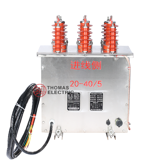
The LSZ-12 is a single-phase, indoor/outdoor rated, cast-resin insulated voltage transformer (VT) engineered for precise voltage transformation in 11kV (IEC nominal) or 10kV (domestic system) medium-voltage networks. Designed in strict accordance with IEC 61869-3 and GB/T 20840.3, this instrument transformer delivers high accuracy for both metering and protective relaying functions across diverse utility and industrial applications. Its core innovation lies in the vacuum pressure impregnation (VPI) epoxy resin insulation system, which fully encapsulates the primary and secondary windings along with the grain-oriented electrical steel (GOES) core, eliminating air voids and moisture ingress pathways.
Operating Principle of Cast-Resin Insulation
Cast-resin insulation in the LSZ-12 employs a two-stage VPI process where pre-wound coils are placed in a mold, evacuated to remove ambient air, and then impregnated under pressure with a thermosetting epoxy resin compound. This results in a monolithic, void-free dielectric structure with exceptional partial discharge resistance—typically below 5 pC at 1.2 × Um/√3. The cured resin exhibits a dielectric strength exceeding 20 kV/mm and a tracking index (CTI) greater than 600, ensuring long-term reliability even in polluted or humid environments. Unlike oil-filled designs, the solid insulation eliminates fire hazards, environmental contamination risks, and maintenance-intensive oil sampling. Thermal conductivity of the resin (~0.8 W/m·K) enables efficient heat dissipation from copper losses, supporting continuous operation at rated load without derating up to 40°C ambient temperature.
Advantages Over Oil-Immersed Designs
Compared to traditional oil-immersed VTs, the LSZ-12 offers significant operational and safety benefits. The absence of flammable insulating oil removes explosion and fire risks, making it suitable for confined spaces such as indoor switchrooms, commercial buildings, and underground substations. Maintenance requirements are drastically reduced—no oil level checks, dielectric testing, or leak repairs are needed over its 25–30-year design life. The compact mechanical footprint (typically 30% smaller than equivalent oil units) facilitates retrofitting into existing switchgear bays. Additionally, the LSZ-12 demonstrates superior seismic resilience due to its rigid monobloc structure, meeting IEC 60068-2-57 Class II requirements for installations in earthquake-prone regions. Environmental compliance is enhanced as the unit contains no PCBs or hazardous liquids, simplifying end-of-life disposal.
Typical Application Overview
The LSZ-12 is deployed across utility distribution networks, industrial plants, renewable energy interconnection points, and railway traction systems. In 11kV ring-main units (RMUs), it provides secondary voltages (e.g., 100/√3 V or 110/√3 V) to revenue meters and digital protective relays. In solar farms, it enables grid-synchronization monitoring and anti-islanding protection by feeding voltage signals to inverters and SCADA systems. Its robust design supports operation in coastal areas with salt fog (IEC 60068-2-52 severity level 6) and high-altitude sites up to 3000 m above sea level (with linear derating per IEC 60071-2). The transformer’s low burden requirement (as low as 1 VA at 0.2 class) ensures compatibility with modern microprocessor-based instrumentation without signal degradation.
Technical Specifications
The LSZ-12 voltage transformer is engineered to deliver consistent performance under defined electrical and environmental parameters. All ratings comply with IEC 61869-3:2011 and GB/T 20840.3-2013, ensuring interoperability in global power systems.
Rated Electrical Parameters
| Parameter | Value |
|---|---|
| System Voltage (Us) | 10 kV (domestic), 11 kV (IEC) |
| Maximum System Voltage (Um) | 12 kV |
| Primary Voltage (Up) | 10/√3 kV, 10.5/√3 kV, 11/√3 kV |
| Secondary Voltage (Us) | 100/√3 V, 110/√3 V (standard); 100 V, 110 V (optional) |
| Voltage Ratio | 10000/100, 10500/100, 11000/100, etc. |
| Accuracy Class (Metering) | 0.2, 0.5 (per IEC 61869-3 Table 101) |
| Accuracy Class (Protection) | 3P, 6P (composite error ≤3% or ≤6% at 5× rated voltage) |
| Rated Output (Burden) | 10 VA, 15 VA, 30 VA (at specified accuracy class) |
| Insulation Level (LI/AC) | 75 kV / 28 kV (1.2/50 μs impulse & 1-min power frequency) |
| Short-Time Withstand Current | Not applicable (VTs are not designed for fault current conduction) |
| Thermal Limit Output | ≥1.5 × rated output continuously without exceeding 120 K temperature rise |
Standard Service Conditions
The LSZ-12 is rated for standard service conditions as defined in IEC 61869-1 Clause 4. Ambient air temperature range is –25°C to +40°C, with an average of +35°C over 24 hours. Relative humidity may reach 100% at 25°C, including condensation. Installation altitude is limited to 1000 m above sea level without derating; for altitudes between 1000 m and 3000 m, the power frequency withstand voltage must be reduced by 1% per 100 m above 1000 m. The unit is suitable for both indoor (pollution degree 2 per IEC 60664-1) and outdoor (IV pollution severity per IEC 60815) environments when mounted vertically with adequate creepage distance (minimum 25 mm/kV for 12 kV Um). Seismic qualification includes horizontal acceleration of 0.3 g (peak ground acceleration) in three orthogonal axes.
Core and Winding Construction
The magnetic circuit utilizes CRGO (cold-rolled grain-oriented) silicon steel laminations with a maximum core loss of 1.0 W/kg at 1.7 T and 50 Hz. Primary windings consist of enameled copper wire (Class F insulation, 155°C thermal rating) wound directly onto the core leg, while secondary windings use double-insulated copper conductors to meet reinforced insulation requirements. Interlayer insulation between primary and secondary is achieved through multiple resin barriers and electrostatic shields, ensuring galvanic isolation with a minimum insulation resistance of 10,000 MΩ at 500 V DC. The entire assembly is post-cured at 130°C for 8 hours to relieve mechanical stresses and optimize resin cross-linking density.
Typical Applications
The LSZ-12 voltage transformer serves critical roles in modern power infrastructure where accuracy, reliability, and safety are paramount.
Substation Secondary Metering
In 11kV primary substations, the LSZ-12 supplies scaled-down voltage signals to revenue-class kWh meters, demand recorders, and power quality analyzers. For example, in a typical urban distribution substation feeding a commercial district, two LSZ-12 units (connected phase-to-ground) provide inputs to a three-phase metering cabinet. With an accuracy class of 0.2 and burden of 10 VA, the transformer ensures billing accuracy within ±0.2% under load conditions ranging from 25% to 100% of rated current. Its low phase displacement error (<10 minutes at 0.2 class) prevents reactive energy measurement drift, crucial for power factor correction billing. The cast-resin housing resists tracking from airborne contaminants common in industrial zones, maintaining dielectric integrity over decades.
Industrial Power Distribution
Large manufacturing facilities often deploy LSZ-12 VTs at the point of supply to monitor incoming 11kV feeders. In a steel mill with arc furnaces, the transformer feeds voltage data to harmonic analyzers and undervoltage relays that trigger automatic load shedding during grid disturbances. The LSZ-12’s ability to withstand transient overvoltages (up to 1.9 × Un for 8 hours per IEC 61869-3) protects downstream electronics from switching surges caused by capacitor bank energization. Its compact size allows integration into metal-enclosed switchgear without requiring external instrument transformer cabinets, reducing footprint and installation costs.
Renewable Energy Integration
Solar photovoltaic (PV) and wind farms utilize the LSZ-12 for grid code compliance monitoring. At a 20 MW solar plant, the VT provides voltage magnitude and phase angle to the plant controller, enabling real-time adjustment of reactive power injection to maintain grid voltage within ±5% of nominal. During islanding events, the rate-of-change-of-frequency (ROCOF) relay uses LSZ-12 outputs to detect disconnection from the main grid within 200 ms. The transformer’s low thermal time constant (≤15 minutes) ensures rapid stabilization after cloud-induced irradiance fluctuations, preventing nuisance tripping of anti-islanding schemes.
Rural and Suburban Distribution Networks
In remote areas with limited maintenance access, the LSZ-12’s maintenance-free design is invaluable. Mounted on pole-top reclosers or pad-mounted transformers, it enables remote voltage monitoring via cellular-connected RTUs. For instance, in a rural electrification project in Southeast Asia, LSZ-12 units installed on 11kV overhead lines feed data to a central SCADA system, allowing utilities to detect voltage sags caused by vegetation contact or conductor damage. The unit’s UV-stabilized resin housing resists degradation from prolonged sun exposure, while its hydrophobic surface sheds rainwater to prevent flashovers during monsoon seasons.
Railway Traction Systems
Although primarily designed for 50/60 Hz systems, the LSZ-12 can be adapted for 16.7 Hz or 25 Hz traction networks with modified core lamination thickness. In European railway substations, it monitors catenary voltage for overvoltage protection of locomotive converters. The transformer’s high short-circuit impedance (typically >3%) limits inrush currents during autotransformer switching, protecting sensitive signaling equipment from electromagnetic interference.
Compliance with International Standards
Conformance to IEC 61869-3 and GB/T 20840.3 ensures the LSZ-12 meets globally recognized benchmarks for safety, accuracy, and durability.
IEC 61869-3 Compliance Details
IEC 61869-3:2011 specifies requirements for inductive voltage transformers for measurement and protection. The LSZ-12 fulfills all mandatory clauses, including: rated insulation levels (Table 2), accuracy limits (Tables 101–103), temperature rise limits (≤60 K for resin at 1.1 × Un), and short-circuit withstand capability (withstanding 2 × Un for 8 hours without damage). Type tests include temperature rise, short-time dynamic behavior, and partial discharge measurements (≤10 pC at 1.2 × Um/√3). Routine tests performed on every unit include turns ratio verification (±0.25% tolerance), polarity check, and power frequency withstand (28 kV RMS for 1 minute). The standard mandates marking of rated voltage factor (1.2 for continuous, 1.5 for 30 s, 1.9 for 8 h), which is permanently engraved on the LSZ-12 nameplate.
GB/T 20840.3 Alignment
China’s national standard GB/T 20840.3-2013 aligns closely with IEC 61869-3 but includes additional requirements for domestic grid conditions. Key differences include: higher impulse withstand level (95 kV vs. 75 kV for 12 kV Um in some provincial grids), mandatory seismic testing per GB/T 13540, and stricter partial discharge limits (≤5 pC at 1.2 × Um/√3). The LSZ-12 is dual-certified, with test reports issued by both international (e.g., KEMA) and Chinese (e.g., China Electric Power Research Institute) laboratories. Domestic installations often specify 10 kV primary voltage with 100 V secondary, whereas IEC projects use 11 kV/100/√3 V configurations—both are supported by the same physical unit through interchangeable winding taps.
Testing and Certification Requirements
Certification involves three test categories: type tests (performed once per design), routine tests (100% production), and special tests (on request). Type tests include: temperature rise (measured via resistance method per IEC 60076-2), short-circuit behavior (applying 2 × Un for 8 h), and electromagnetic compatibility (EMC) immunity to 1 MHz damped oscillatory waves. Routine tests encompass: visual inspection, winding resistance measurement (±2% tolerance), insulation resistance (>10,000 MΩ), and ratio/polarity verification. Special tests may include chopped impulse (1.2/2–5 μs) or seismic shake-table validation. Certificates must reference the exact test standard edition (e.g., IEC 61869-3:2011 + AMD1:2017) and list all measured parameters against acceptance criteria.
On-Site Testing Procedures
Field commissioning of the LSZ-12 requires verification of key parameters to ensure safe and accurate operation.
Insulation Resistance Test
Using a 500 V DC megohmmeter, measure insulation resistance between primary and secondary windings, and between each winding and earth. Acceptance criterion: ≥10,000 MΩ at 20°C. Temperature correction is applied using Rt = R20 × 2(20–t)/10, where t is ambient temperature in °C. Low readings indicate moisture ingress or resin cracking—requiring drying or replacement. This test must be performed before any high-voltage application.
Turns Ratio Test
Apply a low AC voltage (50–100 V) to the primary and measure secondary voltage with a calibrated voltmeter. Calculate actual ratio = Vp/Vs. Compare to nameplate ratio; deviation must be within ±0.25% for 0.2 class units. For multi-tap secondaries, verify each tap independently. Automated ratio testers (e.g., Omicron CT Analyzer) reduce human error and store digital records.
Polarity Test
Confirm reducing polarity (IEC standard) by connecting a 1.5 V battery momentarily across primary terminals (H1–H2). Observe secondary voltage polarity with a DC voltmeter: positive deflection at X1 relative to X2 confirms correct polarity. Incorrect polarity causes 180° phase shift, leading to metering errors and relay misoperation. This test is critical for differential protection schemes.
Power Frequency Withstand Voltage Test
Apply 28 kV RMS (for 12 kV Um class) at 50 Hz between primary and secondary/earth for 1 minute. Use a calibrated test transformer with overcurrent trip set at 10 mA. No flashover or breakdown should occur. For refurbished units, apply 80% of factory test voltage (22.4 kV). Always discharge windings through a grounding stick post-test.
Open-Circuit Characteristic Test
Gradually increase primary voltage from 0 to 190% of rated (e.g., 0–20.9 kV for 11 kV unit) while measuring secondary voltage and excitation current. Plot Vs vs. Iexc. Knee-point voltage should exceed 1.5 × Un; excessive excitation current (>5% of rated) indicates core saturation or turn-to-turn faults. This test validates performance under overvoltage conditions.
Preventive Maintenance Guide
Although cast-resin VTs require minimal maintenance, periodic inspections extend service life and prevent unexpected failures.
Periodic Inspection Protocol
Annual visual inspections should check for: surface cracks or tracking marks on resin, corrosion of terminal studs, loose secondary wiring, and accumulation of conductive dust. Clean housing with dry cloth or low-pressure air (≤2 bar); never use solvents. Verify torque on M10 terminal bolts (25 N·m ±10%). In coastal areas, inspect for salt deposits—remove with deionized water rinse if conductivity exceeds 100 μS/cm. Record ambient temperature and load profile to correlate with historical data.
Maintenance Intervals and Fault Diagnosis
| Interval | Action | Fault Indicators |
|---|---|---|
| Annually | Visual inspection, IR thermography | Hot spots >10 K above ambient indicate winding defects |
| Every 5 years | Insulation resistance, ratio test | Ratio error >0.5% suggests turn shorts |
| After fault event | Full suite of commissioning tests | Elevated PD (>20 pC) implies internal damage |
| End of life (25+ yrs) | Dielectric spectroscopy (tan δ) | tan δ >0.5% at 10 kV indicates aging |
Common failure modes include: partial discharge erosion (from manufacturing voids), thermal runaway (due to sustained overvoltage), and terminal corrosion (in high-humidity environments). If secondary voltage drops suddenly, suspect open-circuit in secondary winding—confirmed by infinite resistance measurement.
Environmental Considerations
In high-pollution areas (IEC pollution severity IV), install silicone rubber sheds over the resin housing to increase creepage distance. For altitudes >2000 m, derate secondary burden by 1% per 100 m to compensate for reduced cooling efficiency. Never paint the resin surface—this traps moisture and accelerates UV degradation. Store spare units horizontally in climate-controlled warehouses (RH <60%) to prevent mechanical stress on terminals.
Conclusion
The LSZ-12 11kV cast-resin voltage transformer represents a mature, field-proven solution for accurate voltage measurement and reliable protection in modern medium-voltage networks. Its VPI epoxy resin insulation system eliminates the fire hazards and maintenance burdens associated with oil-filled alternatives, while delivering exceptional dielectric performance and environmental resilience. Compliance with IEC 61869-3 and GB/T 20840.3 ensures global interoperability and adherence to stringent accuracy, thermal, and safety requirements. With a design life exceeding 25–30 years under standard service conditions, the LSZ-12 minimizes lifecycle costs through zero routine maintenance and high immunity to pollution, humidity, and seismic activity. Its compact form factor facilitates integration into space-constrained switchgear, and the availability of multiple accuracy classes (0.2 for metering, 3P/6P for protection) supports diverse application needs—from utility revenue metering to renewable energy grid interconnection. When installed and tested according to the procedures outlined in this document, the LSZ-12 provides decades of trouble-free operation, making it a cornerstone component in resilient and intelligent power distribution infrastructure.