Article Content
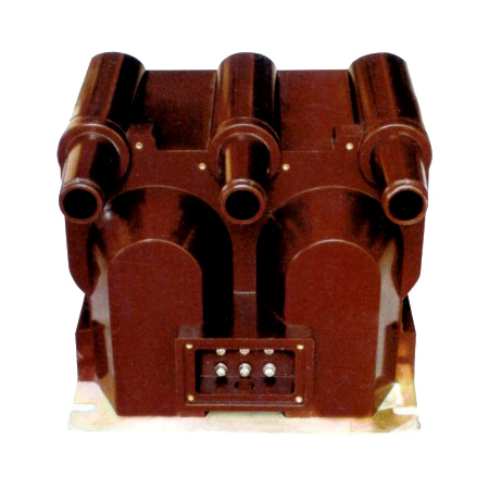
Outdoor/Indoor 11kV Cast-Resin Voltage Transformer MER-1 – IEC 61869-3 Compliant
Introduction to the MER-1 Voltage Transformer
The MER-1 Voltage Transformer (VT) is a precision-engineered instrument transformer designed for reliable operation in 11kV (IEC-rated) or 10kV (domestic system) medium-voltage networks. As a cast-resin insulated device, it provides accurate voltage transformation from high primary potentials to standardized secondary levels—typically 100 V or 100/√3 V—for use in metering, protective relaying, and power quality monitoring systems. Its robust construction ensures electrical isolation between hazardous primary circuits and low-voltage instrumentation, significantly enhancing personnel safety and system integrity.
Operating Principle of Cast-Resin Insulation
Cast-resin insulation in the MER-1 VT employs vacuum pressure impregnation (VPI) technology using cycloaliphatic epoxy resin. This process fully encapsulates the primary and secondary windings along with the magnetic core, eliminating air voids that could lead to partial discharges under sustained operating voltages. The resin matrix exhibits excellent dielectric strength (>20 kV/mm), thermal conductivity (~0.8 W/m·K), and resistance to tracking and erosion in polluted environments. Unlike oil-filled designs, the solid insulation eliminates fire hazards, leakage risks, and maintenance associated with fluid containment. The homogeneous structure also provides superior mechanical rigidity, reducing susceptibility to vibration-induced winding displacement during short-circuit events.
Advantages Over Oil-Immersed Designs
Compared to traditional oil-immersed VTs, the MER-1’s cast-resin construction offers multiple operational benefits. It is inherently non-flammable, making it suitable for indoor installations without fire suppression requirements per IEC 61439. The absence of liquid insulation eliminates the need for conservators, breathers, or oil sampling programs, reducing lifecycle costs. Additionally, the compact footprint—enabled by higher dielectric strength of epoxy versus mineral oil—allows for space-constrained switchgear integration. Environmental resilience is enhanced: the MER-1 operates reliably in ambient temperatures from –40°C to +40°C and withstands humidity up to 100% RH without condensation-related performance degradation. Partial discharge levels are maintained below 10 pC at 1.2 × Um/√3, ensuring long-term insulation integrity.
Typical Applications Overview
The MER-1 is deployed across diverse infrastructure sectors requiring precise voltage measurement and protection coordination. In utility substations, it interfaces with revenue-class meters and distance relays. Industrial facilities utilize it for motor protection schemes and energy management systems. Renewable energy plants—particularly solar PV and wind farms—rely on its stable output for grid synchronization and anti-islanding detection. Its dual compliance with IEC 61869-3 and GB/T 20840.3 enables seamless deployment in both international projects and domestic Chinese grids operating at nominal 10kV. The transformer supports both single-phase and three-phase configurations, with options for residual voltage windings for earth-fault detection in unearthed or compensated neutral systems.
Technical Specifications
The MER-1 VT is engineered to meet stringent performance criteria under defined service conditions. Key parameters are derived from IEC 61869-3:2011 and GB/T 20840.3-2013, ensuring interoperability across global power systems.
| Parameter | Value |
|---|---|
| Primary Voltage (IEC) | 11 kV (Um = 12 kV) |
| Primary Voltage (Domestic) | 10 kV (Um = 11.5 kV) |
| Secondary Voltage | 100 V or 100/√3 V (standard); optional 110 V |
| Voltage Ratio | 11000/100, 11000/100/√3, 10000/100, etc. |
| Accuracy Class (Metering) | 0.2, 0.5 (per IEC 61869-3) |
| Accuracy Class (Protection) | 3P, 6P |
| Rated Output (per burden class) | 10–100 VA (e.g., 30 VA at 0.5 class) |
| Insulation Level (LI/AC) | 75 kV / 28 kV (for 11kV system) |
| Short-Time Thermal Withstand | 1 s at 100 A (secondary short-circuit current) |
| Core Material | Grain-Oriented Electrical Steel (GOES), M4 grade |
| Partial Discharge | <10 pC at 1.2 × Um/√3 |
Standard Service Conditions
The MER-1 is rated for standard service conditions as defined in IEC 61869-1: ambient temperature range of –40°C to +40°C, relative humidity up to 100%, and installation altitude ≤1000 m above sea level. For altitudes exceeding 1000 m, derating factors apply: for every 100 m above 1000 m, the rated insulation withstand voltage must be reduced by 1%. The transformer is suitable for both indoor (pollution degree 2) and outdoor (pollution degree 3) environments when mounted vertically with adequate creepage distance (≥25 mm/kV for 11kV). Condensation is mitigated through hydrophobic resin formulation and sealed terminal chambers.
Accuracy and Burden Characteristics
Accuracy classes are guaranteed within specified burden ranges. For example, a 0.2-class MER-1 maintains ratio error ≤±0.2% and phase displacement ≤±10 minutes when loaded between 25% and 100% of rated burden (e.g., 7.5–30 VA for a 30 VA unit). Protection-class units (3P/6P) ensure composite error ≤3% or ≤6% at rated symmetrical short-circuit current. Burden is expressed in volt-amperes (VA) at cos φ = 0.8 lagging. Exceeding rated burden degrades accuracy and may cause overheating; therefore, secondary circuits must be designed with impedance calculations accounting for cable length, relay input, and meter loading.
Typical Applications
The MER-1 VT serves critical roles across modern power infrastructure due to its reliability, accuracy, and environmental adaptability.
Substation Secondary Metering
In 11kV/10kV distribution substations, the MER-1 provides voltage inputs to revenue meters compliant with IEC 62053-22. Its 0.2-class accuracy ensures billing precision within ±0.2%, meeting regulatory requirements for commercial and industrial consumers. The transformer is typically installed on the busbar or feeder side, with secondary wiring routed to metering panels via shielded cables to minimize electromagnetic interference. In ring-main units (RMUs), its compact design allows integration alongside load-break switches without compromising arc-flash safety distances. Dual secondary windings enable simultaneous connection to both tariff meters and SCADA systems.
Industrial Power Distribution
Large manufacturing plants use the MER-1 for motor protection, power factor correction control, and energy monitoring. For instance, in a steel mill with 10kV induction motors, the VT supplies voltage signals to multifunction relays (e.g., IEC 61850-compliant devices) for undervoltage, overvoltage, and phase-loss detection. The cast-resin body resists chemical fumes and dust common in industrial settings, while the high short-circuit withstand capability ensures survival during downstream fault events. Integration with power quality analyzers allows harmonic distortion monitoring up to the 50th order, supporting compliance with IEEE 519 limits.
Renewable Energy Integration
Solar photovoltaic (PV) and wind power plants operating at 10kV/11kV rely on the MER-1 for grid code compliance. During islanding events, the VT’s stable secondary output enables rapid detection via rate-of-change-of-frequency (ROCOF) or vector shift algorithms. Inverter-based resources require precise voltage magnitude and phase angle data for reactive power control (Q(V) droop). The MER-1’s low phase displacement error (<5 minutes at 0.5 class) ensures accurate synchronization during grid reconnection. Its outdoor rating permits direct mounting on pad-mounted transformers without weatherproof enclosures.
Rural and Suburban Distribution Networks
In rural electrification projects, the MER-1 supports automated feeder monitoring in pole-mounted or ground-level switchgear. Its maintenance-free design reduces operational costs in remote areas with limited technical staff. Used in conjunction with fault indicators and reclosers, it enables sectionalizing of faults on overhead lines. For suburban ring networks, the transformer facilitates load profiling and voltage regulation via remote terminal units (RTUs). The 100/√3 V secondary configuration is standard for three-phase four-wire systems with grounded neutrals, enabling line-to-neutral metering for residential customers.
Compliance with International Standards
The MER-1 VT is certified to IEC 61869-3:2011 (“Instrument transformers – Part 3: Inductive voltage transformers”) and aligns with China’s GB/T 20840.3-2013, ensuring global acceptance and interoperability.
IEC 61869-3 Compliance Details
IEC 61869-3 defines performance, testing, and marking requirements for inductive VTs. The MER-1 meets all clauses, including: rated insulation levels (LI 75 kV, AC 28 kV for 11kV systems), temperature rise limits (≤60 K for resin, ≤50 K for windings), and accuracy verification under defined burdens. Type tests include temperature rise, short-circuit withstand, and impulse voltage tests. Routine tests—performed on every unit—include turns ratio, polarity, and power frequency withstand at 3 kV for 1 min on secondary circuits. Markings include primary/secondary ratings, accuracy classes, burden, and manufacturer data per Clause 10. The standard mandates that protection-class VTs maintain specified accuracy up to 5× rated voltage during transient overvoltages.
GB/T 20840.3 Alignment and Differences
GB/T 20840.3 mirrors IEC 61869-3 but includes localized adaptations. Key differences: GB specifies 10kV as the nominal system voltage (vs. IEC’s 11kV), though insulation levels remain identical (Um = 11.5 kV vs. 12 kV). Accuracy classes are denoted identically (0.2, 0.5, 3P, 6P), but GB requires additional factory tests for partial discharge at 1.2 × Um/√3 with limits ≤10 pC—identical to IEC. However, GB mandates seismic qualification for regions with seismic intensity ≥7 degrees, which the MER-1 achieves via reinforced core clamping and resin anchoring. Both standards prohibit ferroresonance in single-pole VTs; the MER-1 incorporates damping resistors or saturable reactors where required.
Testing and Certification Requirements
Certification involves third-party type testing at accredited laboratories (e.g., KEMA, CESI, or China Electric Power Research Institute). Tests include: lightning impulse (1.2/50 µs wave, 75 kV peak), power frequency dry/wet withstand (28 kV rms for 1 min), and temperature rise (measured via resistance method). Accuracy verification uses calibrated reference VTs traceable to national standards. Each production unit undergoes routine tests: insulation resistance (>1000 MΩ at 2500 V DC), ratio error (within class limits), and polarity (reducing polarity confirmed via DC kick test). Certificates of Conformity list test results and reference IEC/GB clause numbers.
On-Site Testing Procedures
Post-installation verification ensures the MER-1 performs within specifications before energization.
Insulation Resistance Test
Measure insulation resistance between primary winding and ground, and between primary and secondary windings, using a 2500 V DC megohmmeter. Acceptance criterion: ≥1000 MΩ at 20°C. Correct for temperature using RT2 = RT1 × 2(T1–T2)/10. Low readings indicate moisture ingress or resin cracking. Perform before and after power frequency tests to detect insulation degradation.
Turns Ratio Test
Apply a low-voltage AC source (e.g., 100 V) to the primary and measure secondary voltage. Calculate actual ratio: Vp/Vs. Compare to nameplate ratio; tolerance must be within ±0.2% for 0.2-class units. Use a dedicated ratio bridge or digital tester with 0.01% resolution. Ensure secondary burden is disconnected to avoid loading errors.
Polarity Test
Verify reducing polarity using the DC kick method: connect a 6–12 V battery to primary terminals (H1+, H2–) and observe secondary voltage deflection on an analog voltmeter. A momentary positive kick at X1 confirms correct polarity. Incorrect polarity causes 180° phase reversal, leading to metering errors or relay misoperation. Digital multimeters may not capture transient response; analog instruments are preferred.
Power Frequency Withstand Voltage Test
Apply 3 kV rms at 50 Hz between all windings connected together and grounded enclosure for 1 minute. No flashover or breakdown permitted. For primary-to-ground, apply 28 kV rms for 1 min (dry conditions). Use a calibrated test transformer with overcurrent protection set to 10 mA. Ramp voltage at 1 kV/s to avoid transient overstress. Conduct in dry weather (RH < 80%).
Open-Circuit Characteristic Test
For VTs, perform open-circuit test to assess core saturation and excitation current. Gradually increase primary voltage from 0 to 190 V (≈1.9× secondary rated voltage) while measuring secondary voltage and primary current. Plot Vs vs. Iexc. Knee point should exceed 1.5× rated secondary voltage. Excessive excitation current indicates core defects or shorted turns. This test is critical for ferroresonance risk assessment in isolated-neutral systems.
Preventive Maintenance Guide
Although cast-resin VTs are largely maintenance-free, periodic checks extend service life beyond 25 years.
Annual Inspection Protocol
Visually inspect for surface tracking, cracks, or discoloration on the resin housing. Clean with mild detergent if contaminated by salt or industrial deposits. Check terminal tightness (torque: 15 N·m for M8 studs). Measure insulation resistance annually; a >20% drop from baseline warrants investigation. Verify secondary wiring integrity and grounding continuity (<0.1 Ω). In coastal areas, inspect for chloride-induced erosion using UV light to detect early tracking.
Maintenance Intervals and Fault Diagnosis
Table: Recommended Maintenance Schedule
| Interval | Action |
|---|---|
| Annually | Visual inspection, IR scan, insulation resistance |
| 5 Years | Ratio and polarity re-verification, partial discharge screening |
| 10 Years | Full accuracy re-certification (optional) |
Common faults include: (1) Secondary open-circuit during operation—causes core saturation and overvoltage; always short secondary before disconnecting loads. (2) Resin delamination—detected via ultrasonic testing or elevated PD levels. (3) Terminal corrosion—mitigated by using tinned copper lugs and antioxidant compound.
Conclusion
The MER-1 11kV cast-resin voltage transformer represents a benchmark in medium-voltage instrumentation, combining precision engineering with robust environmental resilience. Its compliance with IEC 61869-3 and GB/T 20840.3 ensures global applicability, while the VPI epoxy resin insulation delivers maintenance-free operation for 25–30 years under standard service conditions. Key technical advantages include low partial discharge levels (<10 pC), high accuracy (0.2 class for metering), and immunity to fire hazards—making it ideal for both indoor switchgear and exposed outdoor installations. The use of GOES core material minimizes no-load losses and enhances linearity across the operating range. With rigorous factory and field testing protocols, the MER-1 guarantees reliable voltage transformation for critical applications in utility, industrial, and renewable energy sectors. Its design philosophy prioritizes safety, longevity, and measurement fidelity, establishing it as a cornerstone component in modern power system monitoring and protection architectures.
Frequently Asked Questions (FAQ)
Q1: Can the MER-1 VT be used on a 10kV system even though it’s rated 11kV?
Yes. The 11kV rating refers to the IEC-standardized highest voltage for equipment (Um = 12 kV). Domestic Chinese systems operate at nominal 10kV with Um = 11.5 kV, which falls within the MER-1’s insulation capability (rated for Um = 12 kV). The transformer will function accurately, as voltage ratio is based on primary system voltage. Ensure the secondary burden matches the selected accuracy class.
Q2: What happens if the secondary circuit is left open during operation?
An open secondary circuit in a VT causes the magnetic core to saturate, leading to excessive primary current draw and potentially dangerous overvoltages (several kV) on the secondary terminals. This can damage connected equipment and pose shock hazards. Always short-circuit the secondary terminals with a link before disconnecting any load. The MER-1 includes internal fusing in some variants to mitigate this risk.
Q3: How does temperature affect accuracy?
Temperature impacts winding resistance and core permeability. The MER-1 is designed so that ratio error variation remains within ±0.1% over –25°C to +40°C for 0.2-class units. Extreme cold (<–30°C) may slightly increase phase displacement due to resin contraction, but this stays within IEC tolerance bands. For critical applications, perform site-specific calibration if ambient exceeds standard conditions.
Q4: Is ferroresonance a concern with the MER-1?
Ferroresonance can occur in unearthed systems when a single-pole VT is switched onto a capacitive circuit (e.g., long cables). The MER-1 mitigates this through core design (higher saturation flux density) and optional built-in damping resistors across tertiary windings. System studies should evaluate capacitance-to-ground values; if C0 > 0.5 µF, consider using three-pole VTs or active damping.
Q5: What is the maximum cable length for secondary wiring?
Secondary cable length depends on burden. For a 30 VA, 0.5-class MER-1, total loop impedance must be ≤0.8 Ω (at cos φ = 0.8). Using 2.5 mm² Cu cable (resistance ≈7.4 Ω/km), maximum one-way length is ~50 m. Longer runs require larger conductors (e.g., 4 mm² for 80 m) or higher burden ratings. Always calculate total burden including relay/meter inputs.
Q6: Can the MER-1 be installed horizontally?
No. The MER-1 must be mounted vertically as per IEC 61869-3 Clause 5.3. Horizontal installation alters heat dissipation paths and may cause uneven resin stress, accelerating aging. Mounting brackets are designed for vertical orientation only; deviation >5° from vertical voids warranty.
Q7: What is the expected service life?
Under standard conditions (≤40°C, pollution degree 3), the MER-1 has a design life of 25–30 years. Accelerated aging occurs above 50°C ambient or in severe pollution (e.g., cement dust, salt fog without cleaning). Life extension is possible with annual maintenance and avoidance of repeated overvoltage events.