Article Content
Introduction
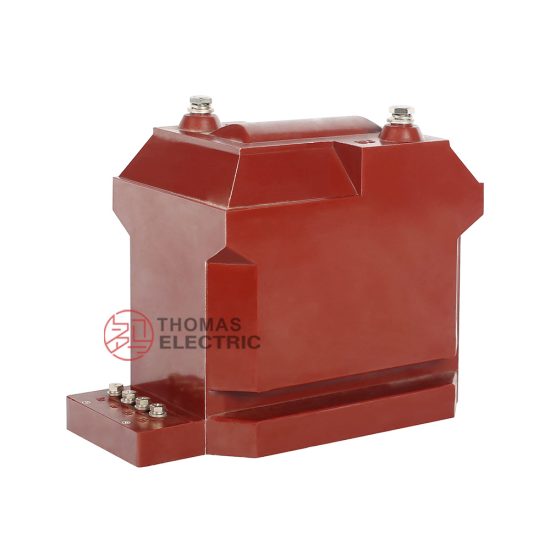
The RZL-10 voltage transformer is a critical component in medium-voltage power systems, specifically engineered for reliable and accurate voltage measurement, protection, and metering applications at the 10 kV level. As part of the resin-cast, indoor-type instrument transformer family, the RZL-10 offers excellent insulation performance, compact design, and long-term operational stability under normal and transient electrical conditions. Its construction utilizes epoxy resin encapsulation, which provides superior mechanical strength, moisture resistance, and fire retardancy—making it ideal for use in switchgear panels, substations, and industrial power distribution networks.
Selecting the appropriate RZL-10 unit requires careful consideration of system parameters, load requirements, and regulatory standards. An improperly specified voltage transformer can lead to inaccurate metering, compromised protective relay coordination, or even equipment failure under fault conditions. This selection guide is designed to assist engineers, designers, and procurement specialists in making informed decisions by detailing key technical aspects: system voltage compatibility, transformation ratio selection, accuracy class requirements, and burden considerations. Understanding these fundamentals ensures that the chosen RZL-10 model delivers optimal performance throughout its service life while complying with international standards such as IEC 61869 and GB/T 20840.
System Voltage
The RZL-10 voltage transformer is rated for nominal system voltages up to 10 kV (line-to-line). However, correct application demands a thorough understanding of both the nominal voltage and the maximum operating voltage of the network. The system voltage determines the insulation level, creepage distance, and dielectric strength required for safe and reliable operation. The RZL-10 is typically used in three-phase systems with either solidly grounded, resistively grounded, or ungrounded neutral configurations, each influencing the voltage stress on the transformer windings during normal and fault conditions.
For a 10 kV system, the highest voltage for equipment (Um) is generally 12 kV according to IEC standards. The RZL-10 is designed to withstand this maximum system voltage continuously without degradation. Additionally, it must endure short-duration power frequency withstand voltages (e.g., 28 kV for 1 minute) and lightning impulse withstand voltages (e.g., 75 kV peak), as verified during type testing. When installing the RZL-10, ensure that the actual system voltage—including potential overvoltages due to switching transients or ferroresonance—remains within the transformer’s rated limits.
Below is a summary of key system voltage parameters relevant to RZL-10 selection:
| Parameter | Symbol | Value for RZL-10 | Standard Reference |
|---|---|---|---|
| Nominal System Voltage | Un | 10 kV (line-to-line) | IEC 60038 |
| Highest Voltage for Equipment | Um | 12 kV | IEC 61869-3 |
| Power Frequency Withstand Voltage (1 min) | Up | 28 kV (rms) | IEC 61869-3 |
| Lightning Impulse Withstand Voltage | Uimp | 75 kV (peak) | IEC 61869-3 |
| Rated Insulation Level | — | 12/28/75 kV | IEC 60071-1 |
Note that in ungrounded or high-resistance grounded systems, the voltage transformer may experience elevated phase-to-ground voltages during single-line-to-ground faults. In such cases, the RZL-10 must be selected with adequate thermal and dielectric margins to handle prolonged overvoltage conditions without insulation breakdown.
Transformation Ratio
The transformation ratio of a voltage transformer defines the relationship between the primary (high-voltage) and secondary (low-voltage) voltages. For the RZL-10, this ratio is crucial for ensuring compatibility with connected instruments, relays, and meters, which typically operate at standardized secondary voltages such as 100 V, 100/√3 V, or 110 V. The most common transformation ratios for 10 kV systems are based on a primary line-to-line voltage of 10,000 V and secondary voltages derived from standard practice.
In three-phase systems, two main secondary configurations are used:
- Line-to-line secondary (100 V or 110 V): Used primarily for metering and protection devices that require phase-to-phase voltage input.
- Line-to-neutral secondary (100/√3 ≈ 57.7 V or 110/√3 ≈ 63.5 V): Employed in systems with grounded neutrals, enabling phase-to-ground voltage measurement and supporting ground-fault detection schemes.
The RZL-10 is often supplied with multiple secondary windings to serve different functions simultaneously—for example, one winding for metering (Class 0.2 or 0.5) and another for protection (Class 3P or 6P). Each winding may have the same or different transformation ratios depending on system architecture.
Selecting the correct ratio involves matching the primary system voltage to the transformer’s rated primary voltage and ensuring the secondary output aligns with the input requirements of downstream equipment. For instance, in a 10 kV system with a solidly grounded neutral, a typical RZL-10 configuration might be:
Primary: 10,000 / √3 V (phase-to-ground)
Secondary: 100 / √3 V (phase-to-ground)
This yields a transformation ratio of (10,000/√3) : (100/√3) = 100:1.
Commonly available transformation ratios for the RZL-10 include:
| Primary Voltage Configuration | Secondary Voltage | Transformation Ratio | Typical Application |
|---|---|---|---|
| 10,000 V (L-L) | 100 V (L-L) | 100:1 | Metering in delta-connected systems |
| 10,000/√3 V (L-N) | 100/√3 V (L-N) | 100:1 | Grounded wye systems, protection & metering |
| 10,000/√3 V (L-N) | 100 V (L-L, open delta) | 100/√3 : 100 | Residual voltage for ground-fault detection |
| 11,000 V (L-L) | 110 V (L-L) | 100:1 | Systems with 11 kV nominal voltage |
| Dual secondary: 100/√3 V + 100/√3 V | Two independent secondaries | 100:1 each | Separate metering and protection circuits |
It is essential to verify that the primary voltage rating of the RZL-10 matches the actual system voltage. Using a transformer rated for 10 kV on an 11 kV system may cause excessive core excitation, leading to increased errors and potential overheating. Conversely, underutilizing the transformer reduces measurement resolution. Always consult the manufacturer’s datasheet for available ratio options and confirm compatibility with your specific network configuration.
Accuracy Class
The accuracy class of a voltage transformer defines the permissible error limits in both ratio error (magnitude) and phase error (angle) under specified load and operating conditions. For the RZL-10, accuracy classes are designated according to IEC 61869-3 and are critical for determining suitability in metering, protection, or auxiliary applications. Common accuracy classes include 0.2, 0.5, 1, 3P, and 6P—where numerical classes (e.g., 0.2) apply to metering, and “P” classes (e.g., 3P) are intended for protection.
Metering accuracy classes (0.2, 0.5, 1) indicate the maximum permissible composite error as a percentage of the rated voltage at burdens ranging from 25% to 100% of the rated burden. For example, a Class 0.2 transformer must maintain a ratio error within ±0.2% and a phase error within ±10 minutes (of arc) when loaded between 25–100% of its rated VA. These tight tolerances are essential for revenue metering and energy billing compliance.
Protection accuracy classes (3P, 6P) prioritize performance during fault conditions, where voltages may deviate significantly from nominal. A Class 3P transformer guarantees that the voltage error does not exceed ±3% and phase error remains below ±120 minutes when subjected to voltages up to 5% of nominal (for ground-fault detection) or up to 190% of nominal (for overvoltage protection), depending on the application. The “P” designation emphasizes reliability under abnormal system states rather than precision at nominal voltage.
The RZL-10 may feature multiple secondary windings, each assigned a different accuracy class. For instance, one secondary might be Class 0.5 for commercial metering, while another is Class 3P for feeding overvoltage relays. The total burden connected to each secondary must not exceed its rated VA (e.g., 30 VA, 50 VA), as exceeding this limit degrades accuracy and may violate class specifications.
| Accuracy Class | Application | Max Ratio Error (%) | Max Phase Error (minutes) | Test Voltage Range |
|---|---|---|---|---|
| 0.2 | Precision metering, revenue billing | ±0.2 | ±10 | 80–120% of Un |
| 0.5 | General metering, substation monitoring | ±0.5 | ±20 | 80–120% of Un |
| 1 | Indicating instruments, non-critical metering | ±1.0 | ±40 | 80–120% of Un |
| 3P | Overvoltage/undervoltage protection | ±3.0 | ±120 | 5–190% of Un |
| 6P | Less sensitive protection schemes | ±6.0 | ±240 | 5–190% of Un |
When selecting an RZL-10 unit, always match the accuracy class to the functional requirement of the connected device. Using a protection-class winding for revenue metering will result in unacceptable billing inaccuracies, while using a high-precision metering winding for protection may compromise relay operation during voltage transients due to saturation or burden mismatch. Additionally, ensure that the total connected burden (including wiring impedance) remains within the rated burden for the declared accuracy class across the expected operating voltage range.
5. Burden Calculation
The burden of a current transformer (CT) is the total impedance presented to its secondary winding, comprising connected devices (relays, meters, etc.) and wiring resistance. Accurate burden calculation ensures the CT operates within its accuracy class and avoids saturation during normal or fault conditions.
Burden is typically expressed in volt-amperes (VA) at a specified power factor or as an impedance (ohms). The total burden \( Z_b \) is calculated as:
\[
Z_b = Z_{\text{lead}} + Z_{\text{device}}
\]
Where:
- \( Z_{\text{lead}} = 2 \rho \frac{L}{A} \) (round-trip resistance of leads)
- \( \rho \) = resistivity of copper (~0.0178 Ω·mm²/m at 20°C)
- \( L \) = one-way lead length (meters)
- \( A \) = cross-sectional area of conductor (mm²)
- \( Z_{\text{device}} \) = input impedance of connected equipment
Example: For a 2.5 mm² copper cable over 50 m (one way) and a relay with 0.1 Ω input impedance:
\[
Z_{\text{lead}} = 2 \times 0.0178 \times \frac{50}{2.5} = 0.712\ \Omega
\]
\[
Z_b = 0.712 + 0.1 = 0.812\ \Omega
\]
At 5 A secondary current, apparent power burden is:
\[
S = I^2 Z_b = 5^2 \times 0.812 = 20.3\ \text{VA}
\]
This exceeds typical 5P10 or 5P20 CT ratings (often 15 VA max), indicating potential inaccuracy. Solutions include using larger conductors (e.g., 4 mm² reduces lead resistance to ~0.445 Ω) or relocating relays closer to the CT.
| Conductor Size (mm²) | Lead Resistance per 100 m (Ω) | Max Recommended Length for 15 VA @ 5 A (m) |
|---|---|---|
| 1.5 | 1.19 | ~25 |
| 2.5 | 0.71 | ~42 |
| 4.0 | 0.45 | ~67 |
| 6.0 | 0.30 | ~100 |
Always verify total burden against the CT’s rated burden (e.g., 5P20-15VA). Exceeding this may cause ratio errors >5% during faults, compromising protection reliability.
6. Short-Circuit Considerations
During short-circuit events, CTs must accurately reproduce primary fault currents in their secondary circuits to ensure protective relays operate correctly. Key parameters include the CT’s accuracy limit factor (ALF) and its ability to avoid saturation under high-magnitude transient currents.
The ALF defines the maximum multiple of rated primary current up to which the CT maintains its stated accuracy (e.g., 5P20 = 5% error up to 20× rated current). However, actual performance depends on the connected burden—higher burden reduces effective ALF.
Transient saturation is critical in high X/R ratio systems (e.g., generator circuits). The DC offset in asymmetrical faults can drive the CT core into saturation before the AC component peaks, distorting the secondary waveform. Mitigation strategies include:
- Selecting CTs with larger cores (higher knee-point voltage \( V_k \))
- Using gapped-core (Class TPX/TPY/TPZ) CTs for differential protection
- Minimizing secondary burden
Knee-point voltage is determined from the excitation curve and should satisfy:
\[
V_k \geq I_{f_{\text{sec}}} (R_{ct} + R_b)
\]
Where:
- \( I_{f_{\text{sec}}} \) = maximum symmetrical secondary fault current
- \( R_{ct} \) = CT secondary winding resistance
- \( R_b \) = total burden resistance
| CT Class | Typical Use Case | Saturation Behavior | Remanence Handling |
|---|---|---|---|
| 5P / 3P | Overcurrent, distance protection | Saturates during long faults | Poor (high remanence) |
| TPX | Line differential (non-teleprotection) | Linear but no air gap | High remanence; requires demagnetization |
| TPY | Busbar/transformer differential | Controlled saturation due to small air gap | Limited remanence (<10%) |
| TPZ | High-speed line protection | Highly linear; defined time constant | Negligible remanence |
For critical applications (e.g., generator differential), perform transient simulation using EMTP or similar tools to validate CT performance under worst-case fault conditions.
7. Environmental Factors
Environmental conditions significantly impact CT performance, longevity, and safety. Designers must account for temperature extremes, humidity, altitude, pollution, and mechanical stress during selection and installation.
Temperature: Standard CTs are rated for –25°C to +55°C ambient. High temperatures accelerate insulation aging; low temperatures may embrittle materials. For outdoor installations in cold climates, specify cold-resistant epoxy or silicone rubber housings.
Altitude: Above 1,000 m, reduced air density compromises insulation and cooling. CTs installed above this altitude require derating or special design (e.g., increased creepage distance, sealed oil-filled units).
Pollution & Humidity: In coastal or industrial areas, salt spray or chemical contaminants can cause tracking and flashover. Use CTs with enhanced creepage (e.g., ≥25 mm/kV) and hydrophobic coatings. Indoor CTs in humid environments should have IP54 or higher ingress protection.
Mechanical Stress: Vibration from nearby transformers or switchgear can loosen connections or damage windings. Secure mounting and flexible leads reduce strain. In seismic zones (e.g., Zone 4 per IEEE 693), CTs must meet dynamic withstand requirements.
| Environment | Recommended CT Features | Standards Reference |
|---|---|---|
| Coastal / High Pollution | RTV-coated porcelain, silicone housing, creepage ≥31 mm/kV | IEC 60815, IEEE C37.90 |
| High Altitude (>2000 m) | Derated rating, sealed construction, increased clearances | IEC 60060-1, IEEE C37.20.2 |
| Sub-zero Temperatures | Low-temp epoxy resin, oil-free design, heater (if enclosed) | IEEE C57.13, IEC 61869-2 |
| Seismic Zones | Anchored base, reinforced core, dynamic testing certification | IEEE 693, IEC 60068-2-57 |
Neglecting environmental factors can lead to premature failure, inaccurate metering, or catastrophic insulation breakdown. Always consult site-specific environmental data during specification.
8. Installation and Verification Checklist
A systematic checklist ensures CTs are correctly selected, installed, and commissioned. Errors in polarity, burden, or grounding can compromise protection schemes or create safety hazards.
| Check Item | Verification Method | Acceptance Criteria |
|---|---|---|
| Correct CT ratio and class | Compare nameplate with single-line diagram | Matches system study (e.g., 1200/5A, 5P20) |
| Polarity orientation | Visual inspection + polarity test (DC kick) | “Dot” or “P1” toward source; relay sees correct phase |
| Secondary burden ≤ rated burden | Measure lead resistance + device impedance | Total ≤ CT rated VA (e.g., ≤15 VA) |
| Grounding of secondary circuit | Inspect grounding point | Single ground at neutral point or relay terminal (never two grounds) |
| Open-circuit prevention | Verify shorting links or test blocks | Secondary never left open during operation |
| Insulation resistance | Megger test (primary-ground, secondary-ground) | >100 MΩ at 1 kV DC |
| Excitation curve validation | Apply variable voltage to secondary, measure current | Knee-point matches manufacturer data |
Final commissioning should include secondary injection testing to confirm relay operation at pickup and time-dial settings. Document all test results for future maintenance and arc-flash studies.