Article Content
Introduction
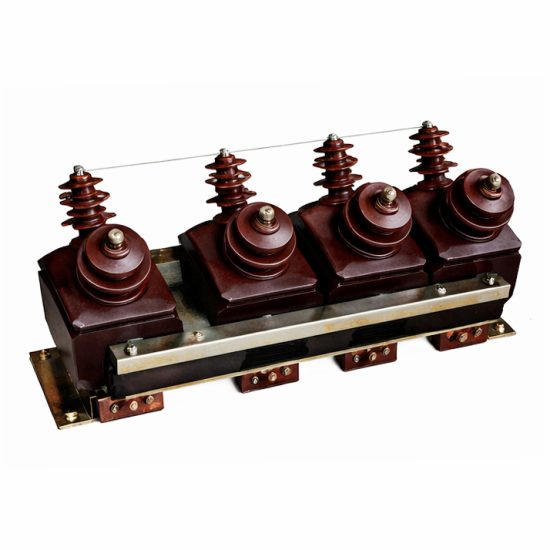
The SZF-3 voltage transformer is a critical component in medium-voltage power systems, specifically engineered for reliable and accurate voltage measurement and protection in 10kV networks. As part of the resin-cast, indoor-type instrument transformer family, the SZF-3 offers excellent insulation performance, compact design, and long-term operational stability under varying electrical and environmental conditions. Its primary role is to step down high system voltages to standardized secondary levels (typically 100 V or 100/√3 V), enabling safe interfacing with metering instruments, protective relays, and monitoring equipment. This isolation not only ensures personnel safety but also enhances the accuracy and longevity of downstream devices by shielding them from high-voltage transients and faults.
Designed in accordance with international standards such as IEC 61869 and GB/T 20840, the SZF-3 incorporates advanced epoxy resin encapsulation technology that provides superior moisture resistance, mechanical strength, and fire retardancy—making it ideal for use in substations, industrial plants, and commercial power distribution systems. The “SZF” designation typically denotes a three-phase, cast-resin voltage transformer with specific structural and thermal characteristics optimized for continuous duty. Understanding the selection criteria for this device is essential to ensure compatibility with system requirements, regulatory compliance, and optimal performance over its service life. This guide addresses key technical parameters that must be evaluated during the specification phase, beginning with system voltage considerations and progressing through transformation ratio, accuracy class, and burden requirements.
System Voltage
Selecting the appropriate SZF-3 voltage transformer requires a thorough understanding of the nominal system voltage and associated insulation levels. The SZF-3 is rated for use in 10kV power systems, which refers to the nominal line-to-line voltage (Un) of the network. However, it is crucial to distinguish between nominal voltage, maximum operating voltage, and the required insulation withstand capability. In practice, 10kV systems often operate within a range of 10–12 kV under normal conditions, with transient overvoltages potentially exceeding these values during switching events or lightning strikes.
The SZF-3 is designed with a highest voltage for equipment (Um) of 12 kV, aligning with standard IEC classifications for 10kV-class apparatus. This ensures adequate insulation margin against both power-frequency and impulse overvoltages. The transformer’s primary winding must be compatible with the system’s grounding configuration—whether solidly grounded, resistance-grounded, or ungrounded—as this affects phase-to-ground voltage stress and the need for residual voltage windings. For example, in an effectively grounded 10kV system (where the neutral is directly or low-impedance grounded), the phase-to-ground voltage is approximately 5.77 kV (i.e., 10 kV / √3), whereas in an ungrounded system, the transformer must withstand full line-to-line voltage (10 kV) on each phase relative to ground during single-line-to-ground faults.
Additionally, the insulation coordination must account for the Basic Insulation Level (BIL). For 10kV equipment, a typical BIL is 75 kV peak for lightning impulse withstand voltage. The SZF-3’s resin-cast construction meets or exceeds this requirement, ensuring robustness in harsh environments. When integrating the transformer into switchgear or ring main units (RMUs), verify clearance and creepage distances per local codes. Mismatched system voltage ratings can lead to insulation failure, inaccurate measurements, or compromised protection schemes.
| Parameter | Symbol | Value for SZF-3 | Standard Reference |
|---|---|---|---|
| Nominal System Voltage | Un | 10 kV (line-to-line) | IEC 60038 |
| Highest Voltage for Equipment | Um | 12 kV | IEC 61869-3 |
| Power-Frequency Withstand Voltage (1 min) | Uw | 28 kV (rms) | GB/T 20840.3 |
| Lightning Impulse Withstand Voltage (BIL) | Up | 75 kV (peak) | IEC 60060-1 |
| System Grounding Compatibility | — | Grounded & ungrounded systems | Application-dependent |
Transformation Ratio
The transformation ratio of a voltage transformer defines the relationship between the primary (system) voltage and the standardized secondary output voltage. For the SZF-3 used in 10kV systems, the most common primary voltage is 10 kV line-to-line, which corresponds to a phase-to-ground voltage of 10/√3 ≈ 5.77 kV in a three-phase, four-wire wye-connected system. Consequently, the standard transformation ratios are selected to produce secondary voltages of either 100 V (line-to-line) or 100/√3 ≈ 57.7 V (phase-to-ground), depending on the metering or protection scheme.
The SZF-3 is typically configured as a three-phase unit with three primary windings connected in star (wye) and three secondary windings also in star, often with an auxiliary delta (open-delta) winding for ground-fault detection. The nominal transformation ratio is expressed as:
Primary Voltage (V1) : Secondary Voltage (V2)
Common configurations include:
- 10,000 / √3 V : 100 / √3 V — Used when secondary phase-to-ground voltage is required (e.g., for phase meters or directional relays).
- 10,000 V : 100 V — Less common for wye systems; typically used in line-to-line measurement applications.
- Dual secondary windings: e.g., (10,000 / √3 V) : (100 / √3 V) + (100 / 3 V) — The second secondary (often called the “residual” or “broken-delta” winding) outputs 100/3 V per phase under balanced conditions and sums to 100 V during ground faults, enabling sensitive earth-fault protection.
It is essential to match the transformation ratio precisely to the system voltage and the input requirements of connected devices. A mismatch can cause significant measurement errors or relay misoperation. For instance, if a meter expects 57.7 V phase-to-ground but receives 100 V due to an incorrect ratio, readings will be 73% higher than actual—a potentially catastrophic error in billing or protection.
Manufacturers often offer the SZF-3 with multiple ratio taps on the primary or secondary windings to accommodate slight variations in system voltage (e.g., 10.5 kV or 11 kV systems). These taps allow field adjustment without replacing the entire unit. Typical tap options might include ±5% or ±2×2.5% adjustments. Always confirm the exact ratio code with the manufacturer based on your system’s nominal and maximum operating voltages.
Furthermore, the vector group must be specified correctly—usually Yyn0d11 or similar—to ensure proper phase alignment between primary and secondary voltages, especially in differential protection or synchro-check applications. Incorrect phasing can lead to false tripping or synchronization failures.
| Primary Voltage Configuration | Secondary Voltage Configuration | Transformation Ratio | Typical Application |
|---|---|---|---|
| 10 kV (L-L) (Star-connected, 5.77 kV L-N) |
100 V (L-L) (57.7 V L-N) |
10,000/√3 : 100/√3 | Metering, general protection |
| 10 kV (L-L) | 100 V (L-L) only | 10,000 : 100 | Line-to-line voltage monitoring |
| 10 kV (L-L) | Main: 100/√3 V Residual: 100/3 V |
(10,000/√3 : 100/√3) + (10,000/√3 : 100/3) | Ground-fault protection (e.g., 64G relays) |
| 10.5 kV (L-L) with taps | 100/√3 V | Adjustable via primary taps (e.g., 10,500/√3 : 100/√3) | Systems with elevated nominal voltage |
Accuracy Class
Accuracy class defines the permissible error limits of a voltage transformer under specified operating conditions, including voltage level, burden, and power factor. For the SZF-3, accuracy is critical because it directly impacts the reliability of energy metering, tariff calculations, and protective relay operations. The SZF-3 is typically available in multiple accuracy classes per IEC 61869-3 and GB/T 20840.3 standards, with common classes including 0.2, 0.5, 1, 3, and 3P/6P for protection.
Measurement accuracy classes (e.g., 0.2, 0.5) specify the maximum permissible composite error (voltage error + phase displacement error) at rated voltage and burden. For instance, a class 0.2 transformer must maintain a voltage error within ±0.2% and a phase error within ±10 minutes (at 0.8 power factor lagging) when operating between 80% and 120% of rated voltage and at burdens from 25% to 100% of rated value. These tight tolerances are essential for revenue metering and high-precision instrumentation.
Protection accuracy classes (e.g., 3P, 6P) are less stringent on voltage error but emphasize performance under fault conditions—specifically, maintaining acceptable accuracy at elevated voltages (up to 190% of rated) that may occur during ground faults in ungrounded systems. A class 3P transformer allows a voltage error of up to ±3% and phase error of ±120 minutes under these extreme conditions, ensuring that overvoltage or undervoltage relays operate correctly even during system disturbances.
Many SZF-3 units feature dual secondary windings: one optimized for measurement (e.g., 0.5 class) and another for protection (e.g., 3P class). It is vital not to connect protection burdens to a measurement-class winding, as the higher fault currents and burdens can drive the core into saturation, degrading accuracy or causing waveform distortion. Conversely, using a protection-class winding for metering may introduce unacceptable billing errors.
The rated burden (expressed in volt-amperes, VA) must also align with the accuracy class. Each class is certified only for burdens within a specified range (e.g., 10–50 VA). Exceeding the rated burden increases errors beyond class limits. Always sum the VA consumption of all connected devices (meters, relays, leads) and include a safety margin (typically 20%) when selecting the transformer’s burden rating.
| Accuracy Class | Application | Voltage Error Limit (%) | Phase Error Limit (minutes) | Operating Voltage Range |
|---|---|---|---|---|
| 0.2 | Precision metering, calibration | ±0.2 | ±10 | 80–120% Un |
| 0.5 | Commercial/industrial metering | ±0.5 | ±20 | 80–120% Un |
| 1 | General indication, non-critical metering | ±1.0 | ±40 | 80–120% Un |
| 3P | Over/undervoltage protection | ±3.0 | ±120 | Up to 190% Un |
| 6P | Less sensitive protection | ±6.0 | ±240 | Up to 190% Un |
5. Burden Calculation
The burden of a current transformer (CT) is the total impedance presented to its secondary winding, comprising connected devices (relays, meters, transducers) and the resistance of the interconnecting wiring. Accurate burden calculation is essential to ensure the CT operates within its rated accuracy class and avoids saturation under normal and fault conditions.
Burden is typically expressed in volt-amperes (VA) at a specified secondary current (usually 1 A or 5 A). The total burden \( Z_b \) is calculated as:
\[
Z_b = Z_{\text{lead}} + Z_{\text{devices}}
\]
where \( Z_{\text{lead}} \) is the loop impedance of the secondary wiring, and \( Z_{\text{devices}} \) is the sum of impedances of all connected equipment.
| Component | Impedance (Ω) | Notes |
|---|---|---|
| Relay Input | 0.05 – 0.2 | Depends on relay type; digital relays often have lower burden |
| Meter Input | 0.1 – 0.5 | Analog meters typically higher than digital |
| Wiring (Round Trip) | \( \frac{2 \times L \times \rho}{A} \) | L = one-way length (m), ρ = resistivity (Ω·mm²/m), A = cross-sectional area (mm²) |
| Connections/Splices | 0.01 – 0.05 | Often neglected but can be significant in long circuits |
For example, with 50 m of 4 mm² copper wire (ρ ≈ 0.0178 Ω·mm²/m), round-trip resistance is:
\[
R_{\text{wire}} = \frac{2 \times 50 \times 0.0178}{4} = 0.445\ \Omega
\]
If connected to a digital relay (0.1 Ω) and a meter (0.2 Ω), total burden = 0.445 + 0.1 + 0.2 = 0.745 Ω. At 5 A secondary current, VA burden = I²Z = 25 × 0.745 ≈ 18.6 VA.
Always compare this calculated burden against the CT’s rated burden (e.g., 15 VA, 30 VA). Exceeding rated burden may cause ratio errors or saturation during faults. Use larger conductor sizes or relocate devices closer to the CT to reduce burden when necessary.
6. Short-Circuit Performance
Current transformers must withstand high short-circuit currents without mechanical damage or loss of accuracy. During system faults, primary currents can reach 20–100 times nominal values. The CT must remain linear (unsaturated) long enough for protective relays to operate correctly—typically within 1–3 cycles.
Key parameters include the symmetrical short-circuit current factor (\( K_{ssc} \)) and the effective symmetrical short-circuit current factor (\( K_{ssce} \)). The CT’s \( K_{ssc} \) rating (e.g., 20, 40) indicates it can handle up to that multiple of rated current without exceeding accuracy limits—provided the actual burden does not exceed the rated burden.
However, if the actual burden is lower than rated, the effective \( K_{ssce} \) increases:
\[
K_{ssce} = K_{ssc} \times \frac{Z_{b,\text{rated}}}{Z_{b,\text{actual}}}
\]
This means a CT rated 20× with 15 VA burden used at 5 VA actual burden has \( K_{ssce} = 20 \times \frac{15}{5} = 60 \)—significantly improving performance during faults.
| Parameter | Description | Typical Values |
|---|---|---|
| Symmetrical Short-Circuit Current Factor (\( K_{ssc} \)) | Max multiple of rated current CT can handle at rated burden | 10, 20, 30, 40 |
| Rated Primary Short-Time Current | Thermal withstand current for 1–3 seconds | 16 kA, 25 kA, 40 kA |
| Rated Dynamic Withstand Current | Peak mechanical force withstand (≈2.5× RMS short-circuit) | 40 kA, 63 kA, 100 kA |
| Time to Saturation | Duration before core saturates under fault current | >20 ms preferred for protection |
Designers must verify that the CT’s \( K_{ssce} \) exceeds the maximum expected fault-to-rated current ratio at the installation point. Failure to do so results in saturated output—flat-topped secondary current—causing relays to under-reach or fail to operate. Use Class PS (Protection Special) or TPX/TPY CTs for critical applications requiring guaranteed transient performance.
7. Environmental Considerations
Environmental factors significantly influence CT selection, installation, and longevity. Outdoor CTs face temperature extremes, humidity, UV exposure, and pollution, while indoor units may encounter dust, chemical vapors, or condensation.
Operating temperature range is critical. Standard CTs are rated for –25°C to +40°C ambient, but extended ranges (–40°C to +55°C) are available for harsh climates. Extreme cold can embrittle insulation and seals; excessive heat accelerates insulation aging and increases copper losses.
Pollution degree affects creepage distance requirements. In coastal or industrial areas with salt spray or conductive dust, CTs must comply with higher pollution degree ratings (e.g., Degree III or IV per IEC 60664), necessitating longer creepage paths between terminals.
| Factor | Impact | Mitigation |
|---|---|---|
| Humidity & Condensation | Reduces insulation resistance; promotes corrosion | Use sealed, gasketed enclosures; silica gel breathers; conformal coatings |
| UV Radiation (Outdoor) | Degrades polymer housings and labels | Select UV-stabilized materials (e.g., cycloaliphatic epoxy) |
| Vibration/Mechanical Shock | Loosens connections; damages core laminations | Secure mounting; anti-vibration pads; robust terminal blocks |
| Altitude | Air density ↓ above 1000 m → reduced cooling & dielectric strength | Derate by 1% per 100 m above 1000 m; use altitude-corrected designs |
Additionally, consider fire safety: CTs in public buildings may require halogen-free, flame-retardant materials (IEC 60754, IEC 60332). For explosive atmospheres (e.g., oil & gas), intrinsically safe or encapsulated designs meeting ATEX/IECEx standards are mandatory. Always consult local codes and environmental site assessments during specification.
8. CT Selection and Verification Checklist
Use this checklist during design review and commissioning to ensure CT suitability and compliance:
| # | Check Item | Status (✓/✗/N/A) |
|---|---|---|
| 1 | Primary current rating matches system load and fault levels | |
| 2 | Secondary current (1 A or 5 A) consistent with relay/meter inputs | |
| 3 | Accuracy class appropriate for application (e.g., 5P20 for protection, 0.5 for metering) | |
| 4 | Calculated total burden ≤ CT rated burden | |
| 5 | Effective \( K_{ssce} \) > maximum fault-to-rated current ratio | |
| 6 | Short-time and dynamic withstand ratings exceed system fault duties | |
| 7 | Environmental rating suitable for location (IP, temperature, pollution) | |
| 8 | Terminal markings comply with IEC 60044 (e.g., P1, P2, S1, S2) | |
| 9 | Core grounded per safety standards (typically at terminal box) | |
| 10 | Open-circuit protection considered (e.g., shorting links, automatic shorting terminals) |
Complete this checklist during both design and site acceptance testing. Any “✗” requires corrective action before energization. Retain the signed checklist in project documentation for audit and maintenance reference.