Article Content
Introduction
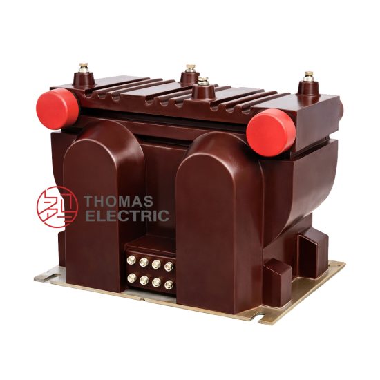
The SZV-10R voltage transformer is a critical component in medium-voltage power systems, specifically engineered for reliable and accurate voltage measurement and protection at the 10 kV level. Designed in accordance with international standards such as IEC 61869 and GB/T 20840, this instrument transformer ensures safe isolation between high-voltage primary circuits and low-voltage secondary instrumentation or relay systems. Its robust epoxy resin encapsulation provides excellent dielectric strength, environmental resistance, and mechanical durability, making it suitable for both indoor switchgear installations and outdoor substations. The SZV-10R supports essential functions including metering, monitoring, control, and protective relaying by delivering scaled-down, proportional secondary voltages that mirror system conditions without exposing sensitive equipment to hazardous potentials. Understanding the selection criteria for this device is vital to ensure compatibility with system requirements, compliance with accuracy demands, and long-term operational reliability. This guide addresses key parameters—system voltage, transformation ratio, and accuracy class—to assist engineers and procurement specialists in specifying the optimal SZV-10R configuration for their application.
System Voltage
Selecting the correct voltage transformer begins with verifying compatibility with the nominal system voltage. The SZV-10R is rated for use in 10 kV class systems, but precise matching requires attention to both the nominal system voltage (Un) and the maximum system voltage (Um). In most distribution networks, the nominal voltage is 10 kV, while the maximum continuous operating voltage typically reaches 12 kV (i.e., Um = 12 kV). The SZV-10R must be rated to withstand this maximum voltage under normal and transient conditions without insulation failure or performance degradation.
The primary insulation level of the SZV-10R is designed for a highest voltage for equipment (Um) of 12 kV, aligning with standard IEC classifications. Additionally, the transformer must endure specified short-duration power frequency withstand voltages (e.g., 28 kV for 1 minute) and lightning impulse withstand voltages (e.g., 75 kV peak), ensuring resilience during switching surges or atmospheric overvoltages. Mismatching the system voltage rating can lead to premature aging, partial discharge activity, or catastrophic insulation breakdown.
It is also essential to confirm whether the system is effectively grounded, resistance-grounded, or ungrounded, as this affects the required voltage factor—the multiplier by which the transformer must operate continuously under abnormal phase-to-ground voltage conditions. For example, in an ungrounded or resonant-grounded system, the SZV-10R may need to sustain 1.9 × Un/√3 for up to 8 hours. Always consult local grid codes and system grounding practices during selection.
| Parameter | Symbol | Value for SZV-10R | Standard Reference |
|---|---|---|---|
| Nominal System Voltage | Un | 10 kV | IEC 60038 |
| Highest Voltage for Equipment | Um | 12 kV | IEC 61869-3 |
| Power Frequency Withstand Voltage (1 min) | — | 28 kV (rms) | IEC 60060-1 |
| Lightning Impulse Withstand Voltage | — | 75 kV (peak) | IEC 60060-1 |
Transformation Ratio
The transformation ratio defines the relationship between the primary and secondary voltages of the SZV-10R and is fundamental to ensuring correct scaling for connected instruments and relays. Expressed as Vp:Vs, this ratio determines how the high system voltage is proportionally reduced to a standardized, safe secondary level—typically 100 V, 100/√3 V, or 110 V, depending on regional practices and application type.
For a 10 kV system, common primary voltages include 10,000 V (line-to-line) or 10,000/√3 ≈ 5,774 V (line-to-neutral in grounded wye systems). The SZV-10R is available in multiple ratio configurations to accommodate these scenarios. For instance, a ratio of 10,000/100 V is used in line-to-line metering applications, while 10,000/√3 : 100/√3 V (often simplified as 10,000:100) is employed in three-phase, four-wire systems where phase-to-neutral voltage measurement is required.
Selecting the appropriate ratio involves more than just voltage scaling—it must align with the burden and wiring configuration of downstream devices. Incorrect ratios can cause significant metering errors or misoperation of protective relays. Moreover, some applications require multiple secondary windings (e.g., one for metering and another for protection), each possibly with different ratios or accuracy requirements. The SZV-10R supports dual-secondary configurations, allowing independent optimization for each function.
Another critical consideration is the vector group and phase displacement. In three-phase systems, the transformer’s connection (e.g., star-star with 0° displacement) must match the system topology to maintain phase coherence across all measurements. Deviations can introduce angular errors that compromise power quality analysis or directional protection schemes.
Finally, verify that the selected ratio complies with local utility specifications. Some regions mandate specific secondary voltages (e.g., 110 V in certain industrial settings), while others standardize on 100 V for interoperability. Always cross-reference the intended application—revenue metering, substation automation, or feeder protection—with the required ratio tolerance and thermal stability under load.
| Primary Voltage (V) | Secondary Voltage (V) | Common Application | Notes |
|---|---|---|---|
| 10,000 | 100 | Line-to-line metering (delta or ungrounded systems) | Single-phase or three-phase, two-wire |
| 10,000/√3 ≈ 5,774 | 100/√3 ≈ 57.7 | Phase-to-neutral metering (grounded wye systems) | Used in 3-phase, 4-wire systems; often labeled as “10,000:100” for simplicity |
| 10,000 | 110 | Industrial control systems (region-specific) | Less common; verify compatibility with relays/meters |
| Dual: 10,000/√3 | 100/√3 (W1) + 100/√3 (W2) | Combined metering & protection | Each winding independently rated; separate burdens allowed |
Accuracy Class
The accuracy class of the SZV-10R voltage transformer defines its permissible error limits in both ratio (magnitude) and phase angle under specified operating conditions. This parameter is crucial because it directly impacts the reliability of energy billing, system monitoring, and protective relay coordination. Accuracy classes are standardized under IEC 61869-3 and typically include designations such as 0.2, 0.5, 1, 3, and 3P/6P (for protection).
For metering applications—especially revenue-grade billing—high accuracy is mandatory. Class 0.2 allows a maximum ratio error of ±0.2% and a phase error of ±10 minutes at 80–120% of rated voltage and at rated burden. Class 0.5 (±0.5% ratio error, ±20 minutes phase error) is acceptable for internal plant metering or non-revenue purposes. In contrast, protection-class windings (e.g., 3P or 6P) prioritize performance under fault conditions rather than precision at nominal voltage. A 3P class permits ±3% ratio error and ±120 minutes phase error at rated voltage, but more importantly, it must maintain defined accuracy up to 5× rated voltage during overvoltage events typical in fault scenarios.
Selecting the correct accuracy class requires evaluating both the application type and the connected burden. Every accuracy class is specified at a particular secondary burden (in VA) and power factor (usually 0.8 lagging). Exceeding the rated burden—even with a high-accuracy transformer—will degrade performance beyond class limits. For example, a Class 0.2 winding rated for 10 VA at 0.8 PF may exhibit Class 1 behavior if loaded with 20 VA.
When the SZV-10R includes multiple secondaries, each winding must be individually assigned an accuracy class appropriate to its function. It is common to specify one winding as Class 0.5 for SCADA telemetry and another as 3P for overvoltage protection relays. Always validate that the total thermal and accuracy requirements do not exceed the transformer’s design limits, particularly under continuous or emergency loading conditions.
| Accuracy Class | Max Ratio Error (%) | Max Phase Error (minutes) | Typical Application | Rated Burden Example |
|---|---|---|---|---|
| 0.2 | ±0.2 | ±10 | Revenue metering, precision calibration | 5–10 VA @ 0.8 PF |
| 0.5 | ±0.5 | ±20 | Internal energy accounting, substation monitoring | 10–30 VA @ 0.8 PF |
| 1 | ±1.0 | ±40 | General indication, non-critical control | Up to 50 VA @ 0.8 PF |
| 3P | ±3.0 | ±120 | Overvoltage, undervoltage protection | Specified at 25–100 VA; valid up to 5× Vn |
| 6P | ±6.0 | ±240 | Basic protection in cost-sensitive applications | Similar to 3P but with wider error band |
5. Burden Calculation
The burden of a current transformer (CT) is the total impedance presented to its secondary winding, comprising connected devices (relays, meters, leads) and wiring. Accurate burden calculation ensures CTs operate within accuracy limits under normal and fault conditions.
| Component | Impedance (Ω) | Description |
|---|---|---|
| Relay/Meter | 0.1 – 2.0 | Input impedance of protective or metering devices; varies by manufacturer and device type. |
| Lead Resistance | 2 × ρL / A | Calculated using resistivity (ρ), one-way length (L), and cross-sectional area (A) of copper/aluminum conductors. |
| Connection Resistance | 0.01 – 0.05 | Contact resistance at terminal blocks or splices; often conservatively estimated. |
| Total Burden (ZB) | Σ Components | Sum of all impedances in series; must be ≤ CT’s rated burden (e.g., 5 VA at 5 A = 0.2 Ω). |
For example, with 100 m of 4 mm² copper leads (ρ ≈ 0.0178 Ω·mm²/m), lead resistance = 2 × (0.0178 × 100) / 4 ≈ 0.89 Ω. Adding a relay (0.3 Ω) and connections (0.03 Ω) yields ZB ≈ 1.22 Ω—exceeding typical 0.2–1.0 Ω ratings, necessitating larger conductors or relocated devices.
6. Short-Circuit Considerations
CTs must withstand mechanical and thermal stresses during short-circuit events without saturation or damage. Key parameters include symmetrical and asymmetrical fault currents, duration, and system X/R ratio.
| Parameter | Typical Value/Range | Impact on CT Performance |
|---|---|---|
| Symmetrical Fault Current | 10–100 kA | Determines required CT accuracy class and knee-point voltage to avoid saturation. |
| Asymmetrical Factor | 1.4–2.0 | Peak current multiplier due to DC offset; higher X/R ratios increase this factor. |
| Fault Duration | 0.05–3 s | Affects thermal withstand capability; longer durations demand higher thermal ratings. |
| Knee-Point Voltage (Vk) | Calculated per IEC 61869 | Vk ≥ If × (RCT + ZB) ensures linear operation during faults. |
Designers must verify that Vk exceeds the voltage developed across the CT secondary during maximum fault: Vsec = Ifault_sec × (RCT + ZB). If Vsec > Vk, the CT saturates, distorting secondary current and compromising protection reliability.
7. Environmental Factors
Environmental conditions significantly influence CT selection, installation, and long-term performance. Key considerations include temperature, humidity, altitude, and pollution levels.
| Factor | Standard Requirement | Mitigation Strategy |
|---|---|---|
| Ambient Temperature | –25°C to +55°C (IEC 61869) | Use temperature-compensated materials; derate if outside range. |
| Humidity | ≤95% non-condensing | Sealed enclosures, conformal coatings, or desiccants for outdoor/harsh environments. |
| Altitude | ≤1000 m (standard); derating above | Increase creepage distance; use altitude-rated insulation for >1000 m. |
| Pollution Degree | Class II–IV (IEC 60664) | Select CTs with appropriate IP rating (e.g., IP54 for dust/moisture resistance). |
Coastal or industrial sites may require CTs with stainless steel housings or epoxy resin encapsulation to resist salt spray or chemical corrosion. Thermal cycling can also induce mechanical fatigue in windings, necessitating robust potting compounds.
8. CT Selection and Verification Checklist
Use this checklist during design, procurement, and commissioning to ensure CT suitability and compliance.
| # | Verification Item | Status (✓/✗) |
|---|---|---|
| 1 | Primary current rating matches system load and fault levels. | |
| 2 | Accuracy class (e.g., 5P20) meets protection/metering requirements. | |
| 3 | Calculated burden ≤ CT rated burden. | |
| 4 | Knee-point voltage sufficient for worst-case fault scenario. | |
| 5 | Thermal and dynamic short-circuit withstand ratings verified. | |
| 6 | Environmental ratings (IP, temperature, altitude) suitable for location. | |
| 7 | Secondary wiring size minimizes burden (typically ≥2.5 mm² Cu). | |
| 8 | Test reports (ratio, polarity, insulation) available and reviewed. |
Final validation should include site acceptance tests (SAT) such as excitation curve measurement and burden verification to confirm as-built performance aligns with design assumptions.