Article Content
Introduction
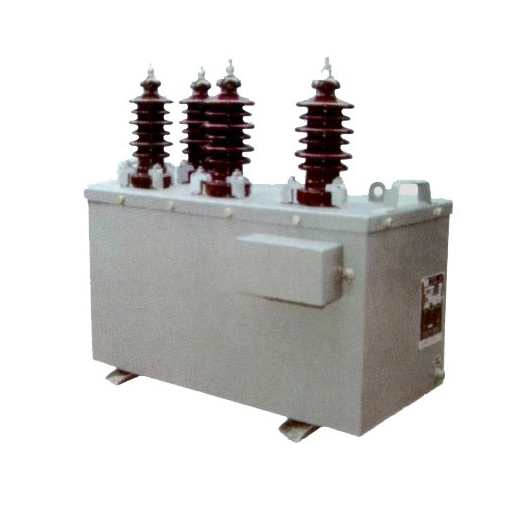
The SZW-10K voltage transformer is a critical component in medium-voltage power systems, specifically engineered for reliable and accurate voltage measurement, protection, and metering applications at the 10 kV level. As part of the electromagnetic voltage transformer family, the SZW-10K converts high primary system voltages to standardized lower secondary voltages—typically 100 V or 110 V—that are compatible with protective relays, energy meters, and monitoring instrumentation. Its robust design ensures long-term operational stability under varying electrical and environmental conditions, making it suitable for use in substations, industrial facilities, and utility distribution networks.
Manufactured in accordance with international standards such as IEC 61869-3 and GB/T 20840.3, the SZW-10K incorporates high-quality magnetic cores, precision winding techniques, and advanced insulation systems to minimize errors and maximize safety. The transformer features a cast-resin insulated body, which provides excellent mechanical strength, moisture resistance, and fire retardancy—essential characteristics for indoor and outdoor installations alike. Furthermore, its compact footprint facilitates easy integration into switchgear panels and ring main units without compromising performance.
Selecting the appropriate SZW-10K unit requires careful consideration of several interrelated technical parameters, including system voltage compatibility, transformation ratio, accuracy class, burden rating, and environmental constraints. This selection guide addresses the first four of these key factors to assist engineers and system designers in specifying the correct model for their specific application. Proper selection not only ensures measurement fidelity and protection reliability but also enhances overall system safety and compliance with regulatory requirements.
System Voltage
The system voltage is the foundational parameter that dictates the suitability of the SZW-10K voltage transformer for a given electrical network. Rated for nominal system voltages up to 10 kV (line-to-line), the SZW-10K is designed to operate continuously within standard voltage ranges defined by IEC and national grid codes. However, it is essential to distinguish between the nominal system voltage, the maximum operating voltage, and the rated insulation level of the transformer.
The SZW-10K is typically specified for systems with a nominal voltage of 10 kV, but it must also withstand transient overvoltages and temporary overvoltages (TOVs) that may occur during switching operations, faults, or resonance conditions. According to IEC 61869-3, the transformer’s insulation level is characterized by its rated lightning impulse withstand voltage (e.g., 75 kV peak) and power frequency withstand voltage (e.g., 42 kV RMS for 1 minute). These values ensure safe operation even under abnormal system stress.
When selecting the SZW-10K, engineers must verify that the transformer’s rated primary voltage matches the system’s phase-to-phase and phase-to-ground configurations. For example, in a 10 kV three-phase system with solidly grounded or resistively grounded neutral, the phase-to-ground voltage is approximately 5.77 kV (i.e., 10 kV / √3). The SZW-10K is commonly connected phase-to-ground, so its primary winding must be rated for this voltage. Mismatched system voltage ratings can lead to insulation failure, inaccurate measurements, or premature aging.
The table below summarizes typical system voltage parameters relevant to SZW-10K selection:
| Parameter | Symbol | Typical Value for SZW-10K | Standard Reference |
|---|---|---|---|
| Nominal System Voltage (line-to-line) | Un | 10 kV | IEC 60038 |
| Maximum Operating Voltage | Um | 12 kV | IEC 61869-3 |
| Phase-to-Ground Voltage (for grounded systems) | Uph | 5.77 kV | Calculated (10 kV / √3) |
| Power Frequency Withstand Voltage (1 min) | Uw | 42 kV RMS | IEC 61869-3 |
| Lightning Impulse Withstand Voltage | Uimp | 75 kV peak | IEC 61869-3 |
Transformation Ratio
The transformation ratio of a voltage transformer defines the relationship between its primary and secondary voltages and is fundamental to ensuring accurate scaling of system voltages for measurement and protection devices. For the SZW-10K, the transformation ratio is expressed as the ratio of the rated primary voltage (phase-to-ground) to the rated secondary voltage. Common secondary voltages include 100 V, 100/√3 V, 110 V, and 110/√3 V, depending on regional standards and application requirements.
In a typical 10 kV system with an effectively grounded neutral, the primary voltage applied to the SZW-10K is 10 kV / √3 ≈ 5774 V (phase-to-ground). If the secondary is rated at 100 / √3 ≈ 57.7 V, the transformation ratio becomes 5774 : 57.7, which simplifies to 100:1. This ratio allows protective relays and meters calibrated for 100 V line-to-line (or 57.7 V phase-to-ground) systems to interface correctly with the 10 kV network.
It is crucial to match the transformation ratio not only to the system voltage but also to the input requirements of downstream devices. For instance, using a 100 V secondary output with a meter designed for 110 V will introduce a consistent scaling error of approximately 10%, leading to inaccurate billing or misoperation of protection schemes. Similarly, dual-secondary windings (e.g., one for metering and one for protection) may have different ratios or burdens, requiring careful coordination during specification.
The SZW-10K is available in multiple standard ratios to accommodate global grid configurations. The following table lists common transformation ratios and their corresponding applications:
| Primary Voltage (V) | Secondary Voltage (V) | Transformation Ratio | Typical Application Region | Connection Type |
|---|---|---|---|---|
| 10000 / √3 ≈ 5774 | 100 / √3 ≈ 57.7 | 100:1 | Europe, Asia (IEC-based) | Phase-to-ground |
| 10000 / √3 ≈ 5774 | 100 | 57.74:1 | Special metering setups | Phase-to-phase (rare) |
| 10000 / √3 ≈ 5774 | 110 / √3 ≈ 63.5 | 91:1 | North America, some industrial | Phase-to-ground |
| 10000 | 100 | 100:1 | Delta-connected systems | Phase-to-phase |
| 10000 / √3 ≈ 5774 | Dual: 100/√3 & 100/√3 | 100:1 (both) | Metering + Protection | Phase-to-ground |
Designers must also consider the impact of ratio selection on burden and accuracy. A mismatched ratio can force secondary devices to operate outside their optimal range, increasing composite error. Additionally, when retrofitting existing systems, the replacement SZW-10K must replicate the original transformation ratio exactly to maintain compatibility with legacy instrumentation. Always consult the equipment nameplate data and system single-line diagrams to confirm the required ratio before procurement.
Accuracy Class
The accuracy class of the SZW-10K voltage transformer defines the permissible limits of its measurement error under specified operating conditions, including voltage level, burden, and power factor. Accuracy is critical because it directly affects the reliability of revenue metering, the sensitivity of protective relaying, and the fidelity of system monitoring. The SZW-10K is manufactured to meet internationally recognized accuracy classes as defined in IEC 61869-3, which categorizes transformers based on their intended application—either for protection or for measurement (metering).
For metering applications, common accuracy classes include 0.2, 0.5, and 1.0. A class 0.2 transformer guarantees that the voltage error does not exceed ±0.2% and the phase displacement remains within ±10 minutes at any load between 25% and 100% of the rated burden (at unity power factor). Higher accuracy classes like 0.2 are typically mandated for fiscal metering points where billing precision is legally regulated. In contrast, class 1.0 may suffice for internal energy management or non-revenue monitoring.
For protection purposes, accuracy classes such as 3P and 6P are used. A 3P-class transformer ensures voltage error ≤ ±3% and phase error ≤ ±120 minutes under fault conditions—often at voltages up to 5× the rated voltage. This broader tolerance is acceptable because protection relays prioritize reliable operation over precision during transients. The “P” designation explicitly indicates suitability for protection circuits.
It is important to note that accuracy is only guaranteed when the transformer operates within its specified burden range (expressed in volt-amperes, VA) and at the rated frequency (typically 50 Hz or 60 Hz). Exceeding the rated burden—by connecting too many instruments or using excessively long secondary cables—increases the load impedance and degrades accuracy. Conversely, operating significantly below the minimum burden can also introduce errors due to core magnetization effects.
The table below outlines standard accuracy classes for the SZW-10K and their typical use cases:
| Accuracy Class | Max Voltage Error (%) | Max Phase Error (minutes) | Application | Typical Burden Range |
|---|---|---|---|---|
| 0.2 | ±0.2 | ±10 | Precision revenue metering | 2.5–30 VA |
| 0.5 | ±0.5 | ±20 | Commercial/industrial metering | 5–50 VA |
| 1.0 | ±1.0 | ±40 | General monitoring | 10–100 VA |
| 3P | ±3.0 | ±120 | Overvoltage, distance protection | Up to 100 VA (at 1–5× Un) |
| 6P | ±6.0 | ±240 | Basic overvoltage detection | Up to 100 VA (at 1–5× Un) |
When specifying the SZW-10K, always align the accuracy class with the functional requirement of the secondary circuit. Mixing a protection-grade (3P) winding with a high-accuracy meter can compromise billing integrity, while using a 0.2-class transformer for simple overvoltage tripping may be unnecessarily costly. Dual-winding models often combine, for example, a 0.5-class metering winding with a 3P protection winding—offering optimal performance for both functions in a single unit.
5. Burden Calculation
The burden of a current transformer (CT) is the total impedance presented to its secondary winding, comprising connected devices (relays, meters, transducers) and interconnecting wiring. Accurate burden calculation is essential to ensure CT accuracy class compliance and prevent saturation during normal or fault conditions.
Burden is typically expressed in volt-amperes (VA) at a specified secondary current (usually 1 A or 5 A). The total burden \( Z_b \) is calculated as:
\[
Z_b = Z_{\text{lead}} + Z_{\text{device}}
\]
Where:
- \( Z_{\text{lead}} = 2 \rho \frac{L}{A} \) (round-trip resistance of leads)
- \( Z_{\text{device}} \) = impedance of connected instrumentation
Key considerations include:
- Use of copper conductors with known resistivity (\(\rho = 0.0178\ \Omega\cdot\text{mm}^2/\text{m}\) at 20°C)
- Accounting for temperature rise (resistance increases ~0.4% per °C)
- Selecting appropriate wire gauge to minimize voltage drop
- Verifying that total burden does not exceed CT-rated burden (e.g., 10 VA, 15 VA)
| Component | Typical Impedance (Ω) @ 5A | Notes |
|---|---|---|
| Electromechanical Relay | 0.05 – 0.20 | Higher for older designs |
| Numerical Relay | 0.01 – 0.05 | Low burden due to electronic input |
| Analog Meter | 0.10 – 0.30 | Depends on movement type |
| Lead Resistance (100 m, 4 mm² Cu) | 0.89 | Round-trip; 2 × (0.0178 × 100 / 4) |
| Total Typical Burden | 0.5 – 2.0 | Must be < CT rated burden |
Exceeding the rated burden shifts the CT operating point toward saturation, distorting secondary current and compromising protection or metering functions. Always perform burden verification during design and commissioning.
6. Short-Circuit Considerations
Current transformers must withstand high-magnitude short-circuit currents without mechanical damage or performance degradation. During faults, primary currents can reach 20–100 times nominal values, imposing significant thermal and electromagnetic forces on CT windings.
Two critical ratings govern short-circuit performance:
- Thermal Withstand Rating: Expressed as \( I_{th}^2 t \) (A²s), representing the energy the CT can absorb without insulation failure. Common values: 1 s, 3 s, or continuous for generator CTs.
- Dynamic (Electrodynamic) Withstand Rating: Peak current (\( I_{dyn} \)) the CT can endure without mechanical deformation, typically 2.5 × \( I_{th} \).
Designers must verify that system prospective short-circuit current (\( I_{sc} \)) satisfies:
\[
I_{sc} \leq I_{th} \quad \text{and} \quad \sqrt{2} \cdot I_{sc} \leq I_{dyn}
\]
Failure to meet these criteria may result in insulation breakdown, winding displacement, or catastrophic failure. Additionally, CT saturation during faults can distort secondary current waveforms, leading to delayed or failed relay operation. To mitigate this:
- Select CTs with adequate accuracy limit factor (ALF)
- Use high-remnant or air-cored CTs for fast-decaying DC offset
- Ensure X/R ratio compatibility with relay algorithms
| Parameter | Symbol | Typical Value | Verification Method |
|---|---|---|---|
| Thermal Withstand Current | \( I_{th} \) | 20–63 kA for 1–3 s | Compare with system \( I_{sc} \) |
| Dynamic Withstand Current | \( I_{dyn} \) | 50–160 kA peak | Check \( \sqrt{2} \cdot I_{sc} \leq I_{dyn} \) |
| Accuracy Limit Factor | ALF | 5–30 | ALF × \( I_n \) ≥ max fault current |
| DC Time Constant | \( T_d \) | 45–150 ms | Affects saturation; match to system X/R |
Always coordinate CT short-circuit ratings with switchgear and protection relay settings to ensure system-wide reliability.
7. Environmental Considerations
Environmental factors significantly influence CT selection, installation, and long-term reliability. Operating conditions such as temperature, humidity, altitude, pollution, and chemical exposure must be evaluated during specification.
Temperature: Standard CTs operate between –25°C to +40°C ambient. For extreme climates:
- High ambient (>40°C): Requires derating or forced cooling
- Low ambient (<–25°C): Risk of oil solidification (in oil-filled CTs) or brittle insulation
Altitude: Above 1000 m, reduced air density decreases dielectric strength and cooling efficiency. CTs rated for high altitude (e.g., up to 3000 m) feature increased creepage distance and derated thermal capacity.
Pollution and Humidity: In coastal, industrial, or dusty environments, use CTs with:
- Increased creepage distance (e.g., 25 mm/kV for heavy pollution)
- Hydrophobic housing (silicone rubber or composite)
- IP54 or higher ingress protection
Chemical Exposure: Avoid PVC housings in areas with ozone or hydrocarbon exposure; prefer UV-stable thermoset resins or stainless steel enclosures.
| Environmental Factor | Standard Rating | Enhanced Requirement |
|---|---|---|
| Ambient Temperature | –25°C to +40°C | –40°C to +55°C (arctic/desert) |
| Altitude | ≤1000 m | Up to 3000 m (with derating) |
| Pollution Degree | II (moderate) | III/IV (heavy industrial/coastal) |
| Ingress Protection | IP20 (indoor) | IP54/IP65 (outdoor/harsh) |
| Humidity | ≤80% non-condensing | Condensation-resistant design |
Always consult IEC 61869-2 and local standards for environmental classification. Field inspections should verify sealing integrity and absence of condensation or corrosion.
8. CT Selection and Installation Checklist
Use this checklist during design review, procurement, and commissioning to ensure reliable CT performance:
| # | Check Item | Status (✓/✗) | Remarks |
|---|---|---|---|
| 1 | Primary current rating matches system full-load current | e.g., 125% of max load | |
| 2 | Secondary current (1A or 5A) compatible with relays/meters | 1A preferred for long cable runs | |
| 3 | Accuracy class meets application (e.g., 5P20 for protection) | Verify ALF ≥ fault current / \( I_n \) | |
| 4 | Total burden ≤ CT rated burden | Include lead resistance | |
| 5 | Thermal & dynamic short-circuit ratings exceed system \( I_{sc} \) | Check \( I_{th} \) and \( I_{dyn} \) | |
| 6 | Environmental rating suitable for location | IP, temp, altitude, pollution | |
| 7 | Core configuration correct (e.g., separate cores for protection & metering) | Avoid shared cores unless validated | |
| 8 | Secondary circuits grounded at single point (typically at CT terminal box) | Prevents circulating currents | |
| 9 | Open-circuit protection installed (shorting links or automatic shorting devices) | Critical for safety | |
| 10 | Polarity marked and verified during commissioning | Essential for differential schemes |
Complete this checklist for every CT installation. Document all verifications and retain records for maintenance and future upgrades.