Article Content
IEC 61869-2 Certified 11kV Cast-Resin Current Transformer SZW-10R for Metering & Protection Applications
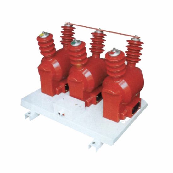
Introduction to the SZW-10R Current Transformer
The SZW-10R is a medium-voltage cast-resin current transformer (CT) engineered for accurate current measurement and dependable protective relaying in 11 kV (IEC-rated) or 10 kV (domestic system) electrical networks. As a core component in substation and industrial power systems, it transforms high primary currents—typically ranging from 50 A to 3000 A—into standardized secondary currents of 1 A or 5 A, enabling safe interfacing with metering instruments, revenue-grade energy meters, and digital protection relays. The design leverages vacuum pressure impregnation (VPI) epoxy resin technology to encapsulate the magnetic core and windings, delivering superior dielectric strength, mechanical robustness, and environmental resilience compared to traditional oil-immersed alternatives.
Operating Principle of Cast-Resin Insulation
Cast-resin insulation in the SZW-10R employs a two-component cycloaliphatic epoxy resin system cured under controlled vacuum and pressure conditions. This VPI process eliminates air voids and microcavities that could initiate partial discharges under sustained operating voltage. The resulting monolithic structure provides a uniform dielectric barrier with a relative permittivity (εr) of approximately 3.8 and volume resistivity exceeding 1×10¹⁴ Ω·cm at 20°C. Unlike oil-filled CTs, which rely on liquid dielectrics prone to leakage and degradation, the solid epoxy matrix offers intrinsic fire resistance (UL 94 V-0 rated), zero maintenance fluid management, and immunity to thermal cycling-induced expansion/contraction stresses. The resin also bonds directly to embedded copper windings and GOES (grain-oriented electrical steel) cores, minimizing interfacial delamination and enhancing long-term thermal stability up to 120°C continuous operation.
Advantages Over Oil-Immersed Designs
The SZW-10R’s cast-resin construction eliminates several failure modes inherent to oil-immersed CTs. First, there is no risk of oil leakage, which can cause environmental contamination, fire hazards in indoor substations, or reduced insulation performance due to moisture ingress. Second, the solid insulation enables compact physical dimensions—typical height of 280 mm and diameter of 160 mm—facilitating retrofit into space-constrained switchgear panels. Third, the absence of breathing mechanisms (e.g., conservator tanks or silica gel breathers) removes a common point of moisture absorption, ensuring stable dielectric properties over decades. Additionally, cast-resin CTs exhibit lower partial discharge levels (<5 pC at 1.2×Um/√3) and higher short-circuit withstand capability (up to 40 kA/1s), critical for fault current interruption in modern distribution networks. These attributes make the SZW-10R particularly suitable for urban substations, data centers, and renewable energy plants where reliability and footprint are paramount.
Typical Application Overview
The SZW-10R serves dual roles in power systems: precision metering and high-speed protection. In utility revenue metering applications, its 0.2S or 0.5S accuracy class ensures compliance with billing regulations under light-load conditions (as low as 1% of rated current). Simultaneously, its 5P10 or 5P20 protection class guarantees linear response during fault transients up to 10–20 times nominal current, enabling correct operation of overcurrent and earth-fault relays. Common deployment sites include 10 kV ring main units (RMUs), pad-mounted transformers, solar inverter output circuits, and industrial motor control centers. Its IP54-rated enclosure supports both indoor switchgear integration and outdoor pole-top mounting, with UV-stabilized resin preventing surface cracking under prolonged solar exposure.
Technical Specifications
The SZW-10R adheres to rigorous electrical and mechanical parameters defined by IEC 61869-2 and GB/T 20840.2. Below is a comprehensive specification table followed by environmental and operational constraints.
| Parameter | Value |
|---|---|
| Rated System Voltage (Um) | 11 kV (IEC), 10 kV (domestic) |
| Rated Insulation Level | 12/28/75 kV (power freq./lightning impulse) |
| Primary Current (Ip) | 50–3000 A (standard); multi-ratio options available |
| Secondary Current (Is) | 1 A or 5 A |
| Accuracy Class (Metering) | 0.2S, 0.5S |
| Accuracy Class (Protection) | 5P10, 5P15, 5P20 |
| Rated Output (VA) | 2.5–30 VA (per burden class) |
| Short-Time Thermal Current | 20–40 kA for 1 s (model-dependent) |
| Dynamic Withstand Current | Up to 100 kA peak |
| Core Material | GOES (Grain-Oriented Electrical Steel), M4 grade |
| Insulation System | VPI Cycloaliphatic Epoxy Resin, Class F (155°C) |
| Ambient Temperature Range | –25°C to +40°C (indoor); –40°C to +45°C (outdoor) |
| Altitude Limit | ≤1000 m above sea level (derating required >1000 m) |
| Relative Humidity | ≤95% non-condensing |
| Ingress Protection | IP54 (terminal box) |
Standard Service Conditions
The SZW-10R is designed for continuous operation under standard service conditions per IEC 61869-2 Clause 5. Ambient temperature must not exceed +40°C average over 24 hours, with a maximum of +45°C for outdoor installations. At altitudes above 1000 m, the dielectric strength decreases by approximately 1% per 100 m; thus, for installations at 2000 m, the lightning impulse withstand voltage must be derated to 67.5 kV. Relative humidity up to 95% is permissible provided condensation does not occur on internal surfaces—a condition ensured by the hermetic nature of the cast-resin body. The transformer assumes a symmetrical three-phase system with balanced loading; unbalanced conditions exceeding 10% negative-sequence current may induce additional heating but remain within thermal limits due to the Class F insulation system (Δθ = 100 K rise at 1.2×In).
Electrical Performance Tolerances
Metering accuracy complies with IEC 61869-2 Table 102: for a 0.2S class CT, ratio error must not exceed ±0.2% and phase displacement ≤±10 minutes at 100% In. At 1% In, the limits relax to ±0.75% and ±30 minutes, respectively—critical for low-load energy accounting. Protection class 5P20 mandates that composite error remains ≤5% when subjected to 20×In with a specified burden (e.g., 15 VA at cos φ = 0.8 lagging). The rated output (burden) is defined at the secondary terminals; exceeding this value increases ratio error nonlinearly. For example, connecting a 30 VA load to a 15 VA-rated winding may degrade 5P20 performance to 5P15. All tolerances assume sinusoidal waveforms with total harmonic distortion (THD) <2%; higher THD requires derating or harmonic-specific CT designs.
Typical Applications
The SZW-10R’s dual-certification and robust construction enable deployment across diverse power infrastructure segments.
Substation Secondary Metering
In 10 kV/0.4 kV distribution substations, the SZW-10R provides revenue-grade current signals to AMI (Advanced Metering Infrastructure) systems. Installed on the medium-voltage side of distribution transformers, it feeds 0.2S-class data to smart meters via shielded twisted-pair cables (e.g., Belden 8761). The CT’s low excitation impedance at light loads ensures minimal phase shift, preserving power factor accuracy essential for reactive energy billing. In China, this configuration satisfies State Grid Corporation’s Q/GDW 1354–2019 requirements for Class 0.5S metering points. The compact form factor allows direct mounting inside SF6-insulated switchgear without auxiliary current transformers, reducing installation cost and potential error sources.
Industrial Power Distribution
Within manufacturing facilities, the SZW-10R monitors feeders supplying large motors (e.g., 1250 kW induction motors at 10 kV). Here, its 5P20 protection class interfaces with numerical relays (e.g., Siemens 7SJ62) to detect phase-to-phase faults within 20 ms. The high dynamic withstand (100 kA peak) accommodates prospective fault currents from upstream grid connections. In environments with high electromagnetic interference (EMI)—such as near variable-frequency drives—the fully shielded resin housing prevents capacitive coupling into secondary circuits. Maintenance teams leverage the IP54 terminal box for safe secondary-side testing without de-energizing the primary busbar, enhancing operational continuity.
Renewable Energy Integration
Solar photovoltaic (PV) plants frequently deploy the SZW-10R on the AC output of central inverters stepping up to 10 kV collection lines. The CT must handle bidirectional current flow and rapid ramp rates during cloud transients. Its GOES core minimizes hysteresis loss under these non-sinusoidal conditions, while the 0.5S accuracy class supports performance-based O&M contracts requiring ±1% energy yield verification. In wind farms, the SZW-10R’s –40°C cold-start capability ensures reliable operation in Nordic or Canadian climates, where oil-filled CTs risk viscosity-related measurement drift.
Rural and Suburban Distribution Networks
For rural electrification projects, the SZW-10R’s outdoor rating (UV-resistant resin, stainless steel hardware) enables pole-top installation on 10 kV overhead lines. It supplies signals to remote terminal units (RTUs) for SCADA-based load profiling and fault location. The 5P10 class provides sufficient saturation margin for typical rural fault levels (8–12 kA), while the 1 A secondary option reduces copper losses over long cable runs (>500 m) to the control house. In India and Southeast Asia, this model meets Central Electricity Authority (CEA) Regulation 58(2) for distribution transformer monitoring.
Compliance with International Standards
The SZW-10R is certified to both global and national standards, ensuring interoperability and regulatory acceptance.
IEC 61869-2 Compliance Details
IEC 61869-2:2012 (“Instrument transformers – Part 2: Additional requirements for current transformers”) governs the SZW-10R’s design validation. Key compliance aspects include: (1) thermal stability verified by temperature-rise tests per Clause 12 (max 60 K for resin, 50 K for terminals); (2) short-circuit performance demonstrated via 1-second thermal and dynamic tests; (3) accuracy verification across 1–120% In using calibrated comparator bridges; and (4) partial discharge measurement at 1.2×Um/√3 with inception/extinction voltages recorded. The standard mandates that protection CTs maintain linearity up to the rated accuracy limit factor (ALF), which for 5P20 is 20×In at specified burden. All test reports are traceable to ISO/IEC 17025-accredited laboratories.
GB/T 20840.2 Alignment
China’s GB/T 20840.2–2014 mirrors IEC 61869-2 but includes localized requirements: (1) mandatory seismic testing for Zone 8 regions (0.2g horizontal acceleration); (2) stricter pollution degree classification (III vs. IEC’s II); and (3) requirement for dual secondary windings (one metering, one protection) in utility applications. The SZW-10R meets these via reinforced core clamping and creepage distance ≥240 mm (vs. IEC’s 200 mm for 12 kV). Notably, GB/T permits 10 kV as the rated voltage (Um = 12 kV), whereas IEC uses 11 kV (Um = 12 kV)—a semantic difference with identical insulation coordination.
Key Differences Between IEC and Domestic Standards
While technical performance is equivalent, administrative differences affect procurement: IEC certification focuses on type testing, whereas GB/T requires batch sampling (1 in 50 units) for routine tests. Additionally, GB/T 20840.2 specifies Chinese-character labeling on nameplates, including the manufacturer’s quality license number. From an engineering standpoint, both standards define identical accuracy classes and test methods; however, GB/T references DL/T 725 for supplementary tests like DC resistance measurement (tolerance ±2% of factory value). For export projects, the SZW-10R carries dual markings: “11 kV IEC” and “10 kV GB” on separate nameplate sections.
On-Site Testing Procedures
Post-installation verification ensures the SZW-10R performs within specifications before energization.
Insulation Resistance Test
Using a 2500 V DC megohmmeter, measure insulation resistance between primary conductor and ground, and between secondary windings and ground. Acceptance criterion: ≥1000 MΩ at 20°C. Correct for temperature using RT = R20 × 2(20–T)/10. Values below 500 MΩ indicate moisture ingress or resin cracking and require drying or replacement. Perform before and after power frequency withstand tests to detect insulation degradation.
Turns Ratio Test
Apply a low-voltage AC source (5–10 V) to the primary and measure secondary voltage. Calculate actual ratio as Vp/Vs; compare to nameplate. Tolerance: ±0.5% for metering classes, ±1% for protection. Use a dedicated turns ratio tester (e.g., Omicron CT Analyzer) for automated comparison against factory curves. Deviations >2% suggest shorted turns or incorrect tap selection.
Polarity Test
Verify reducing polarity per IEC 61869-2 Figure 101: connect a 1.5 V battery momentarily between P1 and P2; observe secondary voltage spike direction with an oscilloscope or analog voltmeter. Positive deflection at S1 confirms correct polarity. Incorrect polarity reverses relay operating torque, causing misoperation during faults. Document results with timestamped waveform captures.
Power Frequency Withstand Voltage Test
Apply 28 kV RMS (50 Hz) for 60 seconds between primary and ground, and between secondary circuits and ground. Monitor for flashover or excessive leakage current (>1 mA). Ramp voltage at 1 kV/s to avoid transient overstress. This test validates insulation integrity after transportation-induced microcracks. Do not perform if partial discharge exceeds 10 pC during pre-test screening.
Short-Circuit Test (for CT)
Inject 10–20×In (e.g., 500 A for a 25 A CT) into the primary with secondary short-circuited. Measure secondary current and calculate composite error: |(KnIs – Ip)| / Ip × 100%. Must be ≤5% for 5P class at rated burden. Use calibrated shunts and high-bandwidth CTs for primary current measurement. This verifies protection performance under fault conditions.
Preventive Maintenance Guide
Proactive maintenance extends service life beyond 25 years.
Periodic Inspection Protocol
Conduct annual visual inspections: check for resin discoloration (indicating UV degradation), terminal corrosion, or tracking marks. Clean surfaces with isopropyl alcohol; never use abrasive cleaners. Verify torque on M8 secondary terminals (12 N·m ±10%). Use infrared thermography during peak load to detect hot spots (>10 K above ambient suggests loose connections). Record findings in asset management software with photo documentation.
Maintenance Intervals and Fault Diagnosis
Every 5 years, perform full electrical tests (insulation resistance, ratio, polarity). Replace if: (1) insulation resistance drops >50% from baseline; (2) ratio error exceeds twice initial tolerance; or (3) partial discharge >20 pC at operating voltage. Common faults include: open secondary circuits (causing core saturation and overheating), moisture in terminal boxes (leading to ground faults), and mechanical stress cracks from improper handling. Always de-energize primary before secondary access—never operate with open secondary.
| Interval | Action |
|---|---|
| Annually | Visual inspection, IR scan, terminal torque check |
| 5 Years | Full electrical tests per Section 5 |
| After Fault | Ratio and insulation tests mandatory |
| End of Life (25–30 yrs) | Replace regardless of test results |
Conclusion
The SZW-10R 11kV cast-resin current transformer represents a benchmark in medium-voltage instrumentation, combining IEC 61869-2 and GB/T 20840.2 compliance with field-proven reliability. Its VPI epoxy resin insulation eliminates the environmental and safety liabilities of oil-filled designs while delivering superior dielectric performance, compact dimensions, and maintenance-free operation across –40°C to +45°C ambient ranges. Engineered with GOES silicon steel cores, it achieves metrological precision (0.2S class) for revenue metering and robust protection characteristics (5P20) for fault detection—even under high-asymmetry transient conditions. Rigorous on-site testing protocols ensure installation integrity, while a structured 5-year maintenance cycle sustains performance over a 25–30 year service life. Deployed globally in utility substations, industrial plants, and renewable energy facilities, the SZW-10R provides a technically sound, standards-compliant solution for accurate current transformation in 10 kV/11 kV networks. Its dual indoor/outdoor rating and resistance to pollution, humidity, and thermal cycling make it particularly suited for demanding environments where long-term operational certainty is non-negotiable. As power systems evolve toward digitalization and distributed generation, the SZW-10R’s compatibility with modern relays and meters ensures continued relevance in next-generation grid infrastructure.