Article Content
Introduction
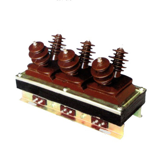
The SZW-6 voltage transformer is a critical component in medium-voltage power systems, specifically engineered for reliable and accurate voltage measurement, protection, and metering applications at the 10kV level. As part of the electromagnetic (inductive) voltage transformer family, the SZW-6 provides galvanic isolation between high-voltage primary circuits and low-voltage secondary instrumentation or relay circuits. This isolation ensures operator safety and protects sensitive equipment from high-energy transients and faults. Designed in compliance with international standards such as IEC 61869-3 and GB/T 20840.3, the SZW-6 offers robust performance under normal and transient operating conditions. Its oil-immersed or resin-cast construction—depending on the specific model variant—ensures excellent dielectric strength, thermal stability, and long-term reliability even in harsh environmental conditions. The transformer’s compact footprint and standardized mounting dimensions facilitate easy integration into switchgear panels, ring main units (RMUs), and outdoor substations. Selecting the appropriate SZW-6 unit requires careful consideration of system parameters including nominal voltage, required transformation ratio, accuracy class, burden rating, and insulation level. This guide aims to assist engineers and procurement specialists in making informed decisions by detailing key selection criteria and technical specifications relevant to 10kV distribution networks.
System Voltage
When selecting an SZW-6 voltage transformer for a 10kV system, it is essential to correctly interpret the system voltage classification to ensure compatibility, safety, and regulatory compliance. The term “10kV” typically refers to the nominal system voltage (Un), but actual operating voltages may vary within defined tolerance bands. According to IEC 60038, the standard voltage series for three-phase AC systems includes 10kV as a preferred value, with a maximum system voltage (Um) of 12kV. The SZW-6 is rated for this Um = 12kV, meaning it can safely operate continuously at up to 12kV and withstand short-duration overvoltages as specified by insulation coordination standards.
The primary winding of the SZW-6 must be matched precisely to the system’s phase-to-phase and phase-to-earth configurations. In most 10kV distribution networks—especially those with isolated neutral or compensated (Petersen coil) grounding—the voltage transformer is connected phase-to-earth. Therefore, the primary voltage rating is typically expressed as a phase-to-earth value: 10,000 V / √3 ≈ 5,774 V. However, some applications may require phase-to-phase connection, necessitating a primary rating of 10,000 V. Misalignment between the transformer’s rated primary voltage and the actual system configuration can lead to measurement errors, overheating, or insulation failure.
Additionally, the insulation level of the SZW-6 must comply with the system’s lightning impulse withstand voltage (LIWV) and power frequency withstand voltage (PFWV). For a 10kV system with Um = 12kV, typical test values are:
| Parameter | Standard Requirement (IEC 61869-3) | SZW-6 Typical Rating |
|---|---|---|
| Power Frequency Withstand Voltage (1 min) | 28 kV (rms) | 30 kV (rms) |
| Lightning Impulse Withstand Voltage (1.2/50 µs) | 75 kV (peak) | 75–95 kV (peak) |
| Maximum System Voltage (Um) | 12 kV | 12 kV |
Always verify local grid codes and utility requirements, as some regions may impose stricter insulation or creepage distance specifications, particularly in polluted or high-altitude environments.
Transformation Ratio
The transformation ratio of a voltage transformer defines the relationship between the primary voltage (high-voltage side) and the secondary voltage (low-voltage side). For the SZW-6 used in 10kV systems, this ratio is a fundamental parameter that directly impacts metering accuracy, relay coordination, and instrument compatibility. The standard secondary voltage for most applications is 100 V or 100/√3 V (≈57.7 V), aligning with international practices for protective relaying and energy metering.
In a typical 10kV unearthed or resonant-grounded system, the SZW-6 is connected phase-to-earth. Thus, the primary voltage per phase is 10,000 V / √3 ≈ 5,774 V. To produce a standard secondary voltage of 100/√3 V (≈57.7 V), the transformation ratio becomes:
Ratio = (10,000 / √3) : (100 / √3) = 100:1
This simplifies to a nominal ratio of 100:1, though it is often denoted as “10,000/√3 V / 100/√3 V” on nameplates to clarify the phase-to-earth connection. Alternatively, if the secondary is wired in open-delta or used for residual voltage detection, a different secondary configuration (e.g., 100/3 V) may be specified.
Common transformation ratios for the SZW-6 in 10kV applications include:
| Primary Voltage (V) | Secondary Voltage (V) | Ratio Notation | Typical Application |
|---|---|---|---|
| 10,000 / √3 | 100 / √3 | 10,000/√3 : 100/√3 | Metering & protection (phase-to-earth) |
| 10,000 / √3 | 100 / 3 | 10,000/√3 : 100/3 | Residual voltage measurement (zero-sequence) |
| 10,000 | 100 | 10,000 : 100 | Phase-to-phase measurement (rare) |
| 10,000 / √3 | 110 / √3 | 10,000/√3 : 110/√3 | Legacy systems or regional standards |
It is crucial to match the transformation ratio not only to the system voltage configuration but also to the input requirements of connected devices. For instance, revenue meters in China and Europe typically expect 100 V or 100/√3 V inputs, while some North American systems may use 120 V secondaries—though the SZW-6 is generally not designed for such markets without customization.
Furthermore, dual-secondary windings are available in certain SZW-6 variants, enabling separate circuits for metering (higher accuracy) and protection (higher burden capacity). In such cases, the ratio remains identical for both secondaries, but their accuracy classes and thermal ratings differ. Always confirm the exact ratio notation on the manufacturer’s datasheet, as misinterpretation (e.g., confusing 100/√3 with 100 V) can result in 73% measurement error.
Finally, note that the actual turns ratio is slightly adjusted during manufacturing to compensate for voltage drop under load (burden), ensuring the secondary voltage remains within accuracy limits at rated burden. This “ratio correction” is factored into the accuracy class certification and should not be altered in the field.
Accuracy Class
The accuracy class of the SZW-6 voltage transformer defines the permissible error in voltage magnitude and phase angle under specified operating conditions. This parameter is critical for applications involving energy metering, tariff billing, and protective relaying, where even small deviations can lead to significant financial or operational consequences. Accuracy classes are standardized under IEC 61869-3 and typically denoted as 0.2, 0.5, 1, 3, or 3P, 6P—where numerical classes (e.g., 0.2) apply to metering and lettered classes (e.g., 3P) to protection.
For metering purposes, common accuracy classes include:
- Class 0.2: Maximum voltage error of ±0.2% and phase error of ±10 minutes at 80–120% of rated voltage and 25–100% of rated burden. Used for precision revenue metering.
- Class 0.5: ±0.5% voltage error, ±20 minutes phase error. Suitable for commercial and industrial sub-metering.
- Class 1: ±1.0% error. General-purpose metering where high precision is not required.
For protection applications, the focus shifts to performance during fault conditions (i.e., at voltages below nominal). Protection classes are designated as “Px” (e.g., 3P, 6P):
- Class 3P: Voltage error ≤ ±3% and phase error ≤ ±120 minutes at 5%–100% of rated voltage and 25–100% of rated burden.
- Class 6P: Voltage error ≤ ±6%, used in less critical protection schemes.
The SZW-6 is commonly available in dual-accuracy configurations—for example, 0.5/3P—where one secondary winding meets metering accuracy (0.5) and another meets protection requirements (3P). The rated burden (expressed in volt-amperes, VA) must also be considered, as accuracy is only guaranteed within the specified burden range (typically 10–50 VA for metering, up to 100 VA for protection).
| Accuracy Class | Application | Voltage Error Limit (%) | Phase Error Limit (minutes) | Typical Burden (VA) |
|---|---|---|---|---|
| 0.2 | Precision metering | ±0.2 | ±10 | 10–30 |
| 0.5 | Commercial metering | ±0.5 | ±20 | 15–50 |
| 1 | General indication | ±1.0 | ±40 | 25–75 |
| 3P | Protective relaying | ±3.0 | ±120 | 30–100 |
| 6P | Backup protection | ±6.0 | Not specified | 50–100 |
Selecting the correct accuracy class involves balancing cost, application criticality, and regulatory requirements. For instance, utility revenue metering often mandates Class 0.2 or 0.5, whereas internal plant monitoring may accept Class 1. Always ensure the total connected burden (sum of all device VA ratings plus wiring losses) does not exceed the transformer’s rated burden for the chosen accuracy class, as excessive burden degrades accuracy and may cause overheating.
5. Burden Calculation
The burden of a current transformer (CT) refers to the total impedance connected to its secondary winding, expressed in volt-amperes (VA) at a specified power factor. Accurate burden calculation is essential to ensure that the CT operates within its accuracy class and does not saturate under normal or fault conditions.
Burden includes the impedance of connected devices such as relays, meters, and wiring. The total burden (\(Z_B\)) is calculated as:
\[
Z_B = Z_{relay} + Z_{wiring} + Z_{connections}
\]
Where:
- \(Z_{relay}\): Impedance of protective or metering relays
- \(Z_{wiring}\): Resistance of secondary wiring (depends on conductor length, cross-section, and material)
- \(Z_{connections}\): Contact resistance at terminals and joints (typically small but non-negligible)
For copper conductors, the resistance per unit length can be approximated using:
\[
R = \frac{\rho \cdot L}{A}
\]
Where \(\rho = 0.0178\ \Omega\cdot\text{mm}^2/\text{m}\) for copper at 20°C, \(L\) is the one-way length (m), and \(A\) is the cross-sectional area (mm²). Since CT circuits are typically looped (go-and-return), total wiring resistance is \(2R\).
Example: A 2.5 mm² copper cable, 50 m one-way length, feeding a relay with 0.1 Ω input impedance:
\[
R_{wire} = \frac{0.0178 \times 50}{2.5} = 0.356\ \Omega \quad \Rightarrow \quad R_{total\_wire} = 2 \times 0.356 = 0.712\ \Omega
\]
\[
Z_B \approx 0.1 + 0.712 = 0.812\ \Omega \quad (\text{assuming resistive load})
\]
\[
\text{Burden (VA)} = I_s^2 \cdot Z_B = (5)^2 \cdot 0.812 = 20.3\ \text{VA}
\]
This exceeds typical 5P10 or 5P20 CT ratings (often rated for 5–15 VA), indicating potential saturation risk. Therefore, either larger conductors or lower-impedance relays must be used.
| Component | Impedance (Ω) | Contribution to Burden (VA @ 5A) |
|---|---|---|
| Protective Relay | 0.10 | 2.5 |
| Wiring (2×50 m, 2.5 mm² Cu) | 0.712 | 17.8 |
| Terminal Connections | 0.05 | 1.25 |
| Total | 0.862 | 21.55 |
To mitigate excessive burden, designers should:
- Use low-burden digital relays (<0.25 VA)
- Increase conductor cross-section (e.g., 4 mm² or 6 mm²)
- Minimize CT secondary run lengths
- Verify CT excitation curves against calculated burden
Accurate burden assessment ensures reliable operation during both steady-state and transient conditions.
6. Short-Circuit Considerations
Current transformers must withstand high short-circuit currents without mechanical damage or loss of accuracy. During system faults, primary currents can reach 20–40 times the nominal rating, inducing large forces and thermal stress in the CT windings.
The key short-circuit parameters include:
- Symmetrical short-circuit current (\(I_{sc}\)): RMS value of AC component
- Asymmetrical (peak) current: Includes DC offset, up to \(2.5 \times I_{sc}\) depending on X/R ratio
- Duration: Typically 1–3 seconds for protection clearing time
CTs are rated for short-time thermal withstand current (e.g., 20 kA for 1 s) and dynamic (mechanical) withstand current (e.g., 50 kA peak). Exceeding these ratings may cause insulation failure, winding deformation, or core displacement.
The thermal withstand capability follows the \(I^2t\) principle:
\[
I_{th}^2 \cdot t_{rated} \geq I_{fault}^2 \cdot t_{clearing}
\]
Where \(I_{th}\) is the rated short-time current, \(t_{rated}\) is the standard duration (usually 1 s or 3 s), and \(t_{clearing}\) is the actual fault clearance time.
Example: A CT rated 20 kA/1s faces a 25 kA fault cleared in 0.8 s:
\[
(20,000)^2 \cdot 1 = 400 \times 10^6\ \text{A}^2\text{s}
\]
\[
(25,000)^2 \cdot 0.8 = 500 \times 10^6\ \text{A}^2\text{s} > 400 \times 10^6
\]
This violates thermal limits—requiring a higher-rated CT (e.g., 25 kA/1s or 20 kA/3s).
| Parameter | System Requirement | CT Rating | Compliance? |
|---|---|---|---|
| Thermal Withstand (Ith) | 25 kA for 0.8 s | 20 kA for 1 s | No |
| Dynamic Withstand | 62.5 kA peak (X/R=15) | 50 kA peak | No |
| Accuracy Limit Factor (ALF) | ≥25 (for 5P20, ALF=20) | 20 | No |
Additionally, the CT’s Accuracy Limit Factor (ALF) must exceed the ratio of maximum fault current to nominal current. For a 1000/5 A CT with 25 kA fault:
\[
\text{Required ALF} = \frac{25,000}{1,000} = 25
\]
A 5P20 CT (ALF=20) is insufficient; a 5P25 or 5P30 class is needed. Failure to meet ALF results in core saturation, distorted secondary current, and potential misoperation of protection relays.
Designers must coordinate CT short-circuit ratings with system studies, ensuring compatibility with breaker interrupting capacity and relay settings.
7. Environmental Considerations
Environmental factors significantly influence CT selection, installation, and long-term reliability. These include temperature extremes, humidity, altitude, pollution, and mechanical stress.
Ambient Temperature: Standard CTs are rated for –5°C to +40°C. In colder climates (e.g., –40°C), special materials (low-temperature epoxy, flexible gaskets) prevent cracking. High ambient temperatures (>40°C) reduce thermal margin, requiring derating or forced cooling.
Altitude: Above 1000 m, air density decreases, reducing dielectric strength and cooling efficiency. CTs installed above 2000 m typically require:
- Increased creepage distance
- Derating of thermal current by ~1% per 100 m above 1000 m
- Special testing per IEC 60060-1
Pollution and Humidity: In coastal or industrial areas, salt spray or chemical contaminants accelerate corrosion and surface tracking. CTs should have:
- IP54 or higher enclosure rating
- Hydrophobic silicone rubber or porcelain housings
- Creepage distance ≥25 mm/kV (medium pollution) or ≥31 mm/kV (heavy pollution)
Mechanical Stress: Seismic zones require CTs tested per IEEE 693 or IEC 60068-2-57. Vibration from nearby transformers or switchgear may loosen connections over time.
| Environment | Key Requirements | Standard Reference |
|---|---|---|
| Cold Climate (–40°C) | Low-temp insulation, impact-resistant housing | IEC 60068-2-1 |
| High Altitude (>2000 m) | Derating, increased clearances | IEC 60694 |
| Coastal/Industrial | IP54+, enhanced creepage, corrosion-resistant hardware | IEC 60815 |
| Seismic Zone | Shock and vibration testing | IEEE 693 (High Qual.) |
Neglecting environmental factors can lead to premature aging, flashovers, or mechanical failure. Always verify manufacturer test reports for site-specific conditions.
8. CT Selection and Verification Checklist
Use this checklist during design, procurement, and commissioning to ensure CT suitability and compliance:
| # | Check Item | Status (✓/✗) | Remarks |
|---|---|---|---|
| 1 | Nominal ratio matches system current (e.g., 1200/5 A) | ||
| 2 | Accuracy class meets application (e.g., 0.5 for metering, 5P20 for protection) | ||
| 3 | Total burden ≤ CT rated burden (VA) | Include wiring, relays, connections | |
| 4 | ALF ≥ (Max fault current / Primary rating) | e.g., 30 kA / 1000 A = 30 → need 5P30 | |
| 5 | Thermal withstand: \(I_{th}^2 t_{rated} \geq I_{fault}^2 t_{clear}\) | Verify with system study | |
| 6 | Dynamic withstand > peak asymmetrical current | Consider X/R ratio | |
| 7 | Environmental rating suitable (temp, IP, altitude, pollution) | Check site conditions | |
| 8 | Secondary wiring uses correct size & material (min. 2.5 mm² Cu) | Reduce burden | |
| 9 | CT polarity marked and verified during commissioning | Critical for differential protection | |
| 10 | Manufacturer test certificates available (ratio, polarity, insulation) | Per IEC 61869 |
This checklist should be completed collaboratively by protection engineers, project managers, and field technicians. Any “✗” item requires corrective action before energization. Regular review during design updates ensures continued compliance.