Article Content
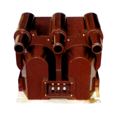
Outdoor/Indoor 11kV Cast-Resin Voltage Transformer XGW-12 – IEC 61869-3 Compliant
Introduction to the XGW-12 Voltage Transformer
The XGW-12 is a single-phase, electromagnetic voltage transformer (VT) designed for accurate voltage transformation in 11kV (IEC nominal) or 10kV (domestic system) medium-voltage networks. Engineered per IEC 61869-3 and GB/T 20840.3, this device provides standardized secondary outputs (typically 100 V or 100/√3 V) for metering, protection relaying, and control systems. Its core function is to step down high primary voltages to safe, measurable levels while maintaining phase fidelity and minimal ratio error under varying load and fault conditions.
Operating Principle of Cast-Resin Insulation
The XGW-12 employs vacuum pressure impregnation (VPI) epoxy resin technology to encapsulate both primary and secondary windings around a grain-oriented electrical steel (GOES) core. During manufacturing, windings are placed in a mold, evacuated to remove air pockets, and then flooded with low-viscosity epoxy under pressure. This process ensures complete void-free encapsulation, eliminating partial discharge risks inherent in oil-filled or dry-wound alternatives. The cured resin forms a monolithic, hydrophobic structure with high dielectric strength (≥20 kV/mm), excellent tracking resistance (CTI ≥600), and superior mechanical rigidity. Unlike oil-immersed VTs, the cast-resin design eliminates fire hazards, environmental contamination risks, and maintenance-intensive oil sampling procedures. The insulation system is rated for continuous operation at 12 kV RMS and withstands lightning impulse voltages up to 75 kV peak per IEC 61869-3.
Advantages Over Oil-Immersed Designs
Compared to traditional oil-filled VTs, the XGW-12 offers significant operational and safety benefits. First, it is inherently non-flammable—critical for indoor switchgear, urban substations, and confined spaces where fire codes prohibit combustible fluids. Second, the solid resin matrix prevents moisture ingress, ensuring stable dielectric performance even in high-humidity coastal or tropical environments (up to 95% RH). Third, the absence of oil eliminates the need for periodic oil testing, degassing, or leak repairs, reducing lifecycle costs by an estimated 30–40%. Additionally, the compact, lightweight design (typically 35–45 kg) simplifies handling and mounting on poles, crossarms, or within ring main units (RMUs). Finally, the thermal stability of epoxy resin allows consistent accuracy across a wide ambient temperature range (–40°C to +40°C), whereas oil viscosity changes can affect magnetic coupling in extreme climates.
Typical Applications Overview
The XGW-12 serves as a foundational component in secondary systems requiring precise voltage representation. It is commonly deployed in 11kV/10kV distribution substations for revenue metering (Class 0.2 or 0.5S), overvoltage/undervoltage protection (Class 3P or 6P), and synchro-check functions. In industrial facilities, it feeds protective relays monitoring motor starters, capacitor banks, and arc-fault detection systems. Renewable integration projects—such as solar farms or wind parks—use the XGW-12 to provide grid-synchronization signals and power quality data to SCADA systems. Its dual-environment rating (indoor/outdoor) enables flexible deployment in pad-mounted transformers, overhead line reclosers, and underground cable distribution networks without derating.
Technical Specifications
The XGW-12 adheres to stringent electrical and mechanical parameters defined by international standards. Below is a comprehensive specification table followed by environmental and operational constraints.
| Parameter | Value |
|---|---|
| Primary Voltage (Up) | 11 kV (IEC) / 10 kV (GB) |
| Secondary Voltage (Us) | 100 V or 100/√3 V (standard); 110 V optional |
| Voltage Ratio | 11000/100, 11000/100/√3, 10000/100, etc. |
| Accuracy Class (Metering) | 0.2, 0.5, 0.2S, 0.5S |
| Accuracy Class (Protection) | 3P, 6P |
| Rated Output (VA) | 10, 15, 30, 50, 100 VA per burden class |
| Insulation Level (LI/AC) | 75 kV / 28 kV (1 min) |
| Short-Time Thermal Withstand | 1 s at 10× rated primary current (for fault conditions) |
| Frequency | 50 Hz or 60 Hz |
| Core Material | Grain-Oriented Electrical Steel (GOES), M4 grade |
| Insulation System | VPI Epoxy Resin, UL 94 V-0 rated |
| Weight | Approx. 40 kg |
| Dimensions (H×W×D) | 680 × 220 × 220 mm |
Standard Service Conditions
The XGW-12 is rated for normal service conditions as defined in IEC 61869-3: ambient temperature from –40°C to +40°C, daily average not exceeding +35°C; relative humidity up to 95% at +25°C; altitude ≤1000 m above sea level (with derating factor of 1.1% per 100 m above 1000 m); and pollution degree III (moderate industrial or coastal environments). Installation must avoid direct exposure to chemical vapors, conductive dust, or explosive atmospheres unless housed in IP54-rated enclosures. For altitudes exceeding 2000 m, consult manufacturer for adjusted insulation coordination.
Accuracy and Burden Characteristics
Accuracy classes define permissible errors under specified burdens. For example, a Class 0.2S VT must maintain ratio error ≤±0.2% and phase displacement ≤±10 minutes at 20–100% of rated burden. Protection-class VTs (e.g., 3P) tolerate ±3% ratio error but prioritize linear saturation characteristics during transient overvoltages. The XGW-12’s GOES core minimizes hysteresis loss, enabling stable accuracy even at 25% of rated burden—a critical feature for modern digital meters with low input impedance. Burden selection must account for total loop impedance: e.g., 50 VA at 100 V implies maximum allowable impedance of 200 Ω (Z = V²/S).
Typical Applications
The versatility of the XGW-12 stems from its dual compliance with IEC and GB standards, robust construction, and precision performance across diverse grid architectures.
Substation Secondary Metering
In 11kV/0.4kV distribution substations, the XGW-12 supplies voltage inputs to three-phase kWh meters for utility billing. Installed on the HV busbar, it typically operates in a wye configuration with grounded neutral, delivering 100/√3 V per phase. Class 0.2S accuracy ensures compliance with regulatory requirements for revenue metering, minimizing commercial losses due to measurement drift. The cast-resin body resists condensation in unheated kiosks, preventing insulation degradation that could skew readings over time. Integration with AMI (Advanced Metering Infrastructure) systems relies on the VT’s stable phase angle, critical for power factor and reactive energy calculations.
Industrial Power Distribution
Large manufacturing plants use the XGW-12 to monitor feeders supplying motors, furnaces, and HVAC systems. Here, protection-class (3P) units feed voltage-restrained overcurrent relays or undervoltage lockout circuits. During motor startup surges or capacitor bank switching, the VT must maintain linearity to prevent nuisance tripping. The XGW-12’s high saturation point (>2.0 pu) ensures reliable operation during temporary overvoltages. Its compact size allows retrofitting into legacy switchgear without panel modifications, and the absence of oil eliminates explosion risks in paint booths or chemical processing areas.
Renewable Energy Integration
Solar photovoltaic (PV) farms connect to 10kV/11kV grids via inverters requiring precise grid voltage for anti-islanding and synchronization. The XGW-12 provides this reference signal to the plant controller and protection relays (e.g., 27/59 functions). In wind turbine step-up transformers, it enables low-voltage ride-through (LVRT) compliance by accurately detecting grid dips. The VT’s fast response time (<20 ms) and low harmonic distortion (<0.5% THD at rated load) ensure clean waveform capture for power quality analyzers. Outdoor UV-stabilized resin housing withstands decades of desert or alpine exposure without cracking.
Rural and Suburban Distribution Networks
Pole-mounted XGW-12 units serve remote villages and suburban neighborhoods where space and maintenance access are limited. Mounted alongside reclosers or sectionalizers, they enable automated fault location and voltage regulation via SCADA. The 10kV domestic variant aligns with China’s GB standard grid, while the 11kV version suits IEC-based networks in Southeast Asia, Africa, and Latin America. With no oil to leak or absorb moisture, these VTs operate reliably in monsoon seasons or arid climates, reducing outage durations caused by instrument failure. Their 30-year design life matches the asset cycle of distribution transformers.
Compliance with International Standards
The XGW-12 is engineered to satisfy both global and regional regulatory frameworks, ensuring interoperability and safety across markets.
IEC 61869-3 Compliance Details
IEC 61869-3 specifies performance, testing, and marking requirements for inductive voltage transformers. The XGW-12 meets all clauses, including: rated insulation levels (LI 75 kV, AC 28 kV); accuracy verification at 80%, 100%, and 120% of rated voltage; temperature rise limits (<60 K for resin, <50 K for windings); and short-circuit withstand capability. Type tests include lightning impulse (1.2/50 µs wave), partial discharge (<10 pC at 1.2 Um/√3), and thermal stability. Routine tests cover ratio, polarity, and power frequency withstand. Markings include primary/secondary ratings, accuracy class, vector group (e.g., II or Yyn), and manufacturer ID per Clause 10.
Alignment with GB/T 20840.3
China’s GB/T 20840.3 mirrors IEC 61869-3 but includes localized requirements: primary voltage tolerance of ±10% (vs. IEC’s ±5%), mandatory seismic qualification for Zone II installations, and stricter harmonic immunity (≤0.3% error at 3rd harmonic injection). The XGW-12’s domestic 10kV variant incorporates these adaptations while retaining IEC compatibility. Notably, GB/T mandates a 1-minute AC withstand test at 32 kV (vs. IEC’s 28 kV) for 10kV systems, which the XGW-12 exceeds with a 35 kV margin.
Key Differences Between IEC and Domestic Standards
While harmonized, subtle differences affect procurement and testing. IEC uses 11kV as the nominal system voltage (Un), whereas GB uses 10kV—requiring separate ratio labeling. IEC permits Class 0.2 for general metering, but GB often requires 0.2S for smart grid applications. Environmental testing under GB includes salt fog (ASTM B117) for coastal zones, absent in IEC base standards. Certification bodies also differ: IEC units carry CB Scheme marks, while GB-compliant models require CQC certification. Dual-marked XGW-12 units simplify export to both markets.
On-Site Testing Procedures
Post-installation verification ensures the XGW-12 performs within specifications before energization.
Insulation Resistance Test
Using a 2500 V DC megohmmeter, measure insulation resistance between primary winding and ground, and between secondary windings and ground. Acceptance criterion: ≥1000 MΩ at 20°C. Correct for temperature using RT = R20 × 2(20–T)/10. Low readings indicate moisture ingress or resin cracking—requiring drying or replacement. Perform before and after AC withstand tests to detect insulation damage.
Turns Ratio Test
Apply a low-voltage AC source (50–200 V) to the primary and measure secondary voltage. Calculate actual ratio: Ractual = Vp/Vs. Compare to nameplate ratio; tolerance must be within ±0.2% for Class 0.2, ±0.5% for Class 0.5, and ±3% for Class 3P. Use a dedicated ratio bridge (e.g., Omicron CT Analyzer) for precision. Deviations suggest winding shorts or incorrect tap selection.
Polarity Test
Verify reducing polarity per IEC 61869-3 Annex B. Connect a 6–12 V battery across primary terminals (H1+, H2–). Momentarily close the circuit while monitoring secondary with a DC voltmeter (X1+, X2–). A positive kick confirms correct polarity. Incorrect polarity causes 180° phase reversal, leading to metering errors or relay misoperation in differential schemes.
Power Frequency Withstand Voltage Test
Apply 28 kV RMS (for 11kV VT) at 50 Hz between primary and ground for 1 minute. Secondary windings are short-circuited and grounded. Monitor for flashover, excessive leakage current (>1 mA), or audible discharge. Failure indicates insulation defects. Reduce test voltage by 20% if performed after transport to avoid overstressing aged insulation.
Open-Circuit Characteristic Test
Gradually increase primary voltage from 0 to 190 V (≈1.9× rated secondary) while measuring excitation current. Plot V vs. I curve; knee point should exceed 1.5× rated voltage. Excessive magnetizing current at rated voltage indicates core saturation or inter-turn faults. This test validates protection-class performance during overvoltage transients.
Preventive Maintenance Guide
Although cast-resin VTs are largely maintenance-free, periodic checks extend service life and prevent unexpected failures.
Periodic Inspection Protocol
Conduct annual visual inspections: check for surface tracking, UV degradation (chalky residue), mechanical damage, or loose terminations. Clean housing with isopropyl alcohol if contaminated by salt or dust. Verify torque on terminal bolts (12 N·m for M8 studs). Use infrared thermography during peak load to detect abnormal heating at connections (>10 K above ambient). Record secondary voltage under no-load; deviations >1% from baseline warrant further testing.
Maintenance Intervals and Fault Diagnosis
Every 5 years, perform full electrical tests (ratio, insulation resistance, open-circuit curve). Replace VT if: insulation resistance drops below 500 MΩ; ratio error exceeds twice the accuracy class limit; or partial discharge exceeds 20 pC. Common faults include cracked resin (from impact or thermal cycling), moisture-induced surface leakage, and secondary winding opens (from vibration fatigue). Note that internal faults are rarely repairable—replacement is standard practice due to encapsulation.
| Interval | Action |
|---|---|
| Annually | Visual inspection, IR scan, terminal torque check |
| Every 5 Years | Full electrical test suite per IEC 61869-3 Clause 12 |
| After Major Fault | Ratio and insulation test before re-energization |
| End of Life (25–30 yrs) | Proactive replacement regardless of condition |
Conclusion
The XGW-12 11kV cast-resin voltage transformer represents a mature, reliable solution for modern medium-voltage infrastructure. By leveraging VPI epoxy resin encapsulation and GOES core technology, it delivers exceptional accuracy, environmental resilience, and safety compared to legacy oil-filled designs. Its dual compliance with IEC 61869-3 and GB/T 20840.3 enables seamless deployment across global markets—from urban substations in Europe to rural microgrids in Southeast Asia. Rigorous factory and field testing protocols ensure long-term performance stability, while minimal maintenance requirements reduce total cost of ownership. With a design life of 25–30 years under standard service conditions, the XGW-12 provides a future-proof foundation for metering, protection, and control systems in evolving smart grids. Its robustness against pollution, humidity, and thermal stress makes it particularly suited for harsh or remote environments where reliability is non-negotiable. As distribution networks integrate more distributed energy resources, the demand for precision voltage sensing will only grow—solidifying the role of high-integrity VTs like the XGW-12 in grid modernization efforts.
Frequently Asked Questions (FAQ)
Q1: Can the XGW-12 be used on a 10kV system if labeled for 11kV?
Yes. The 11kV rating refers to the IEC nominal system voltage (Un = 11 kV), which corresponds to a maximum operating voltage (Um) of 12 kV. Domestic 10kV systems (per GB) have Um = 11.5 kV or 12 kV, falling within the XGW-12’s insulation envelope. The VT will operate accurately as long as the actual system voltage stays within ±10% of its rated primary voltage (i.e., 9.9–12.1 kV for an 11kV unit). Always verify the voltage ratio matches your secondary requirements (e.g., 11000/100 V vs. 10000/100 V).
Q2: What is the maximum secondary burden for a Class 0.2S XGW-12?
The maximum burden is defined by the rated output (e.g., 30 VA). For a 100 V secondary, Zmax = V²/S = 100²/30 ≈ 333 Ω. However, accuracy is only guaranteed between 25% and 100% of rated burden per IEC 61869-3. Operating below 25% (e.g., 7.5 VA) may increase ratio error beyond Class 0.2S limits due to core magnetization effects. Always calculate total loop impedance—including meter, relay, and wire resistance—and select a VT with sufficient output margin.
Q3: Is the XGW-12 suitable for indoor GIS switchgear?
Yes, provided the enclosure meets IP2X or higher. The cast-resin design emits no gases or fluids, making it ideal for sealed environments. However, ensure adequate creepage distance: IEC 61869-3 requires ≥240 mm for 11kV in pollution degree III. The XGW-12’s standard housing provides 300 mm, sufficient for most indoor applications. For SF6-insulated GIS, confirm compatibility with gas decomposition byproducts—epoxy resin is generally resistant.
Q4: How does temperature affect XGW-12 accuracy?
Temperature impacts core permeability and winding resistance. The XGW-12 is compensated to maintain accuracy within class limits from –25°C to +40°C. Outside this range, errors may increase: e.g., at –40°C, ratio error could drift by an additional ±0.1% due to reduced core flux density. For critical applications in extreme climates, request extended temperature testing data from the manufacturer.
Q5: Can multiple secondary windings be paralleled?
No. Paralleling secondaries creates circulating currents due to minute ratio mismatches, causing overheating and accuracy loss. Each secondary must feed independent burdens. If higher output is needed, select a single winding with greater VA rating (e.g., 100 VA instead of two 50 VA windings).
Q6: What causes partial discharge in cast-resin VTs?
Although rare, PD can occur due to manufacturing voids, thermal aging cracks, or surface contamination creating field enhancements. The XGW-12 undergoes 100% PD testing (<10 pC at 1.2 Um/√3) at the factory. Field PD usually indicates physical damage—inspect for impact marks or tracking. Continuous PD monitoring is recommended for critical assets.
Q7: Is seismic qualification available?
Yes. Standard XGW-12 units meet IEC 60068-2-57 for Zone 1 (0.3g horizontal). For high-seismic zones (e.g., China Zone II, 0.5g), reinforced core clamping and base brackets are available—consult the manufacturer for certified test reports.