Article Content
Introduction
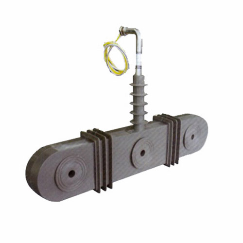
The ZW-10 Current Transformer is a critical component in medium-voltage power systems, specifically engineered for reliable and accurate current measurement and protection in 10kV networks. As part of the broader family of instrument transformers, the ZW-10 enables safe interfacing between high-voltage primary circuits and low-voltage secondary instrumentation—such as relays, meters, and monitoring devices—by stepping down the primary current to standardized, manageable levels (typically 1A or 5A). This isolation not only ensures operator safety but also enhances the precision and longevity of connected equipment. Designed with robust epoxy resin insulation and a compact, maintenance-free structure, the ZW-10 meets stringent international standards including IEC 61869 and GB/T 20840, making it suitable for indoor switchgear installations in utility substations, industrial plants, and commercial power distribution systems. Its performance directly influences the reliability of protective relaying schemes and the accuracy of energy billing, underscoring the importance of proper selection based on system parameters, load characteristics, and application requirements.
System Voltage
Selecting the appropriate ZW-10 current transformer requires careful consideration of the system voltage to ensure both operational safety and compliance with insulation standards. The “10” in ZW-10 denotes its nominal system voltage rating of 10kV (kilovolts), which corresponds to a maximum operating voltage of 12kV as per IEC classifications. This rating defines the highest continuous phase-to-phase voltage the transformer can withstand under normal service conditions. It is essential to match the CT’s voltage class precisely with the network voltage; using a ZW-10 in a system exceeding 12kV risks insulation breakdown, partial discharge, and catastrophic failure. Conversely, deploying it in significantly lower-voltage systems (e.g., 6kV) is technically permissible but may result in suboptimal cost-efficiency and oversized physical dimensions.
The ZW-10 is designed for three-phase AC systems with a frequency of 50Hz or 60Hz. Its insulation system—comprising cast epoxy resin with embedded silica filler—provides excellent dielectric strength, tracking resistance, and environmental stability. The transformer undergoes rigorous testing, including power frequency withstand voltage (42kV for 1 minute) and lightning impulse withstand (75kV peak), ensuring resilience against transient overvoltages common in distribution networks. Below is a summary of key voltage-related specifications:
| Parameter | Value | Standard Reference |
|---|---|---|
| Nominal System Voltage (Un) | 10 kV | IEC 61869-3 |
| Maximum System Voltage (Um) | 12 kV | IEC 60038 |
| Power Frequency Withstand Voltage | 42 kV (1 min) | IEC 61869-1 |
| Lightning Impulse Withstand Voltage | 75 kV (peak) | IEC 61869-1 |
| Rated Insulation Level | 12/42/75 kV | IEC 60071-1 |
Note that ambient conditions—such as altitude, humidity, and pollution degree—can affect insulation performance. For installations above 1000 meters altitude, derating or special design variants may be required to maintain clearance and creepage distances.
Transformation Ratio
The transformation ratio (also known as the turns ratio) is a fundamental specification of the ZW-10 current transformer, defining the relationship between the primary current (Ip) and the secondary current (Is). Expressed as Ip:Is, common ratios include 50:5, 100:5, 200:1, 400:5, and up to 3000:5 or higher, depending on the model variant. This ratio determines how much the primary current is scaled down for measurement or protection purposes. For instance, a 600:5 ratio means that a 600A current in the primary circuit produces a proportional 5A output on the secondary winding.
Selecting the correct ratio involves analyzing both normal load currents and potential fault currents. The primary current rating should exceed the maximum expected continuous load current (typically 1.2 to 1.5 times the full-load current) to avoid saturation during normal operation, while still allowing sufficient sensitivity for protection functions during faults. Undersizing the ratio leads to core saturation under overload conditions, causing inaccurate readings and delayed relay tripping. Oversizing reduces measurement resolution at light loads, particularly affecting metering accuracy.
The ZW-10 often features multi-ratio or tapped secondary windings, enabling flexibility in field configuration. For example, a single unit might offer taps at 200/400/600:5A, allowing adaptation to changing system requirements without hardware replacement. When multiple cores are present (e.g., one for metering and another for protection), each may have an independent ratio optimized for its specific function.
Key considerations when selecting the transformation ratio include:
- Load Profile: Analyze historical and projected load data to determine typical and peak currents.
- **Protection Coordination:** Ensure the ratio allows protective relays to detect minimum fault currents reliably.
- **Secondary Burden Compatibility:** The chosen ratio must align with the impedance of connected devices (meters, relays, leads) to prevent excessive voltage drop and ratio errors.
- **Future Expansion:** Selecting a slightly higher ratio can accommodate load growth over the asset’s lifecycle.
The table below illustrates common ZW-10 transformation ratios and their typical applications:
| Primary Current (A) | Secondary Current (A) | Common Ratio Notation | Typical Application |
|---|---|---|---|
| 50 | 5 | 50:5 | Small feeders, lighting circuits |
| 100 | 5 | 100:5 | Distribution transformers (≤250 kVA) |
| 200 | 1 | 200:1 | Low-burden digital relays |
| 400 | 5 | 400:5 | Main incomers, motor feeders |
| 800 | 5 | 800:5 | Substation bus couplers |
| 1500 | 5 | 1500:5 | Large industrial services |
Always verify that the selected ratio complies with local utility requirements and that the secondary current standard (1A vs. 5A) matches existing instrumentation infrastructure.
Accuracy Class
The accuracy class of the ZW-10 current transformer defines the permissible error limits in both current magnitude and phase angle under specified operating conditions. This parameter is crucial because it directly impacts the fidelity of measurements for billing (metering) and the dependability of protective relaying. Accuracy classes are standardized by IEC 61869 and vary depending on whether the CT is used for metering or protection.
For metering applications, common accuracy classes include 0.2, 0.5, and 1.0. A class 0.2 CT guarantees that the composite error does not exceed ±0.2% at rated current and specified burden, making it suitable for revenue-grade energy metering. Class 0.5 is typically used for internal plant accounting, while class 1.0 suffices for general monitoring. These classes are valid within a defined current range—usually from 5% to 120% of rated primary current—and at a specific secondary burden (e.g., 10 VA at cos φ = 0.8).
Protection-class CTs, on the other hand, are designated with suffixes like 5P or 10P (where “P” stands for protection). A 5P10 rating means the CT maintains a composite error within ±5% when subjected to 10 times the rated primary current, provided the burden does not exceed the rated value. Similarly, 10P20 allows ±10% error at 20× overcurrent. These ratings ensure that during fault conditions—when currents surge dramatically—the CT output remains sufficiently accurate to enable correct relay operation.
It is vital to distinguish between metering and protection accuracy requirements. Using a metering-class CT for protection may lead to severe saturation during faults due to its smaller core, resulting in relay misoperation. Conversely, a protection-class CT lacks the precision needed for accurate energy measurement at low load levels.
The table below summarizes typical ZW-10 accuracy classes and their performance criteria:
| Accuracy Class | Application | Max Composite Error | Current Range | Example Rating |
|---|---|---|---|---|
| 0.2 | Metering (Revenue) | ±0.2% | 5%–120% In | 0.2 / 10 VA |
| 0.5 | Metering (Sub-metering) | ±0.5% | 10%–120% In | 0.5 / 15 VA |
| 5P10 | Protection | ±5% at 10× In | Up to 10× In | 5P10 / 15 VA |
| 10P20 | Protection (High Fault) | ±10% at 20× In | Up to 20× In | 10P20 / 30 VA |
When specifying the ZW-10, always define the accuracy class in conjunction with the rated burden (in volt-amperes, VA) and power factor, as errors increase with higher burden. Additionally, for dual-core units, each core must be independently rated—e.g., one core as 0.5/10VA for metering and another as 5P10/15VA for protection.
5. Burden Calculation
The burden of a current transformer (CT) is the total impedance presented to its secondary winding, comprising connected devices (relays, meters, leads) and wiring. Accurate burden calculation ensures CT accuracy class compliance and prevents saturation during normal or fault conditions.
| Component | Typical Burden (VA or Ω) | Description |
|---|---|---|
| Protective Relay | 0.5 – 5 VA | Digital relays typically consume less than electromechanical types. Manufacturer datasheets specify exact values. |
| Metering Device | 1 – 10 VA | Energy meters and panel meters contribute significantly; verify at rated current. |
| Lead Resistance | R = ρL/A (Ω) | Calculated using resistivity (ρ), total loop length (L), and conductor cross-section (A). For 4 mm² copper over 50 m: ~0.43 Ω. |
| Connection Terminals | 0.05 – 0.2 Ω | Contact resistance at terminal blocks and test switches adds minor but non-negligible burden. |
| Total Burden (Zb) | Σ(All above) | Must be ≤ CT’s rated burden (e.g., 15 VA at 5 A → Zrated = 0.6 Ω). |
Example: A CT feeds a digital relay (1 VA), a meter (3 VA), and 60 m of 2.5 mm² copper wire (R ≈ 0.82 Ω). At 5 A, lead burden = I²R = 25 × 0.82 = 20.5 VA. Total burden = 1 + 3 + 20.5 = 24.5 VA. If the CT is rated for 15 VA, this exceeds capacity—requiring larger conductors or closer device placement.
6. Short-Circuit Considerations
During short-circuit events, CTs must accurately reproduce high-magnitude primary currents without saturating, ensuring protective relays operate correctly. Key parameters include symmetrical and asymmetrical fault currents, X/R ratio, and CT saturation voltage.
| Parameter | Requirement | Notes |
|---|---|---|
| Maximum Fault Current | ≥ System prospective fault level | Obtained from system studies (e.g., 40 kA RMS symmetrical). |
| X/R Ratio | Match system X/R at CT location | High X/R (>15) increases DC offset, demanding higher saturation voltage. |
| Saturation Voltage (Vk) | Vk ≥ If × (Zb + Rct) | If = fault current referred to secondary; Rct = CT winding resistance. |
| Accuracy Limit Factor (ALF) | ALF ≥ Ifault,sec / Irated,sec | e.g., 5P20 CT can handle 20× rated current within ±5% error. |
Designers must verify that the CT’s knee-point voltage exceeds the voltage developed across the total burden during worst-case faults. Failure to do so causes saturation, distorting secondary current and potentially blocking relay operation. Transient performance may require special cores (e.g., PR or PX class per IEC 61869).
7. Environmental Factors
Environmental conditions significantly impact CT performance, longevity, and safety. Installations must account for temperature, humidity, altitude, pollution, and mechanical stress.
| Factor | Impact | Mitigation |
|---|---|---|
| Ambient Temperature | Extreme heat/cold affects insulation integrity and core permeability. | Select CTs rated for -40°C to +70°C (or project-specific range). |
| Humidity & Condensation | Promotes corrosion and tracking on terminals/insulation. | Use sealed, gasketed enclosures; conformal coating on PCBs in electronic CTs. |
| Altitude >1000 m | Reduced air density lowers dielectric strength. | Apply altitude correction factors; increase creepage distance. |
| Pollution Degree | Dust, salt, or chemical deposits cause surface leakage. | Specify IP65/NEMA 4X enclosures; use silicone rubber or EPDM insulation. |
| Vibration & Seismic Activity | Loosens connections; damages brittle components. | Secure mounting with anti-vibration pads; comply with IEEE 693 or IEC 60068-2. |
For outdoor substations near coastal areas, salt fog testing (per IEC 60068-2-52) is recommended. Indoor switchgear in industrial plants may require enhanced protection against oil mist or metallic dust.
8. CT Selection and Installation Checklist
Use this checklist during design review and commissioning to ensure compliance, safety, and reliability.
| # | Check Item | Status (✓/✗) | Remarks |
|---|---|---|---|
| 1 | Primary current rating matches max continuous load + margin. | e.g., 120% of normal load. | |
| 2 | Accuracy class suitable for application (protection vs. metering). | 5P/10P for protection; 0.5/0.2 for metering. | |
| 3 | Total burden ≤ CT rated burden. | Include leads, relays, meters. | |
| 4 | Short-circuit withstand verified (ALF, Vk). | Based on system fault study. | |
| 5 | Environmental ratings match site conditions. | IP, temperature, pollution class. | |
| 6 | Secondary circuits grounded at single point (per IEEE C57.13). | Prevents circulating currents. | |
| 7 | No open-circuit risk during maintenance (test blocks used). | Mandatory for safety. | |
| 8 | Polarity marked and verified during installation. | Critical for differential and directional schemes. |
This checklist should be completed by the design engineer and validated by the commissioning team. Any “✗” requires corrective action before energization.