Article Content
Introduction
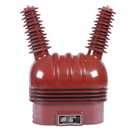
The JDZW-35K voltage transformer is a cast-resin insulated instrument transformer designed for accurate voltage measurement and reliable protective relay operation in medium-voltage power systems. Although commonly referenced as a 35 kV device under Chinese domestic standards (GB/T 20840), its primary rated voltage aligns with the international standard of 33 kV as defined by IEC 61869-3. This dual designation reflects regional differences in nominal system voltages: 33 kV is typical in many IEC-compliant networks, whereas 35 kV is used in certain domestic applications within China. The transformer is suitable for both indoor and outdoor installations, offering robust performance across a range of environmental conditions.
Engineered to meet stringent accuracy and insulation requirements, the JDZW-35K supports critical functions in electrical substations, including revenue metering, system monitoring, and protective relaying. Its construction adheres to the latest editions of IEC 61869-3 (Instrument transformers – Part 3: Additional requirements for inductive voltage transformers) and GB/T 20840 (Chinese national standard series for instrument transformers). This document provides a comprehensive technical overview of the transformer’s specifications, features, applications, installation guidelines, testing protocols, and maintenance practices to assist engineers in proper selection, deployment, and lifecycle management.
Technical Specifications
The JDZW-35K voltage transformer is a single-phase, cast-resin insulated unit designed for use in three-phase systems. Its primary rated voltage is 33 kV (line-to-ground), consistent with IEC 61869-3, while the equivalent domestic rating per GB/T 20840 is 35 kV. The secondary windings are typically configured for metering and protection outputs, with standard secondary voltages of 100/√3 V or 100 V, depending on system grounding configuration.
- Primary Voltage: 33 kV (IEC standard); 35 kV (GB/T 20840 equivalent)
- Secondary Voltage: 100/√3 V (for wye-connected systems) or 100 V (for open-delta or line-to-line connections)
- Frequency: 50 Hz (standard); 60 Hz optional upon request
- Insulation Level:
- Lightning Impulse Withstand Voltage (LI): 170 kV peak
- Power Frequency Withstand Voltage (AC): 70 kV rms for 1 minute
- Accuracy Classes:
- Metering winding: Class 0.2, 0.5, or 0.2S (per IEC 61869-3 and GB/T 20840.3)
- Protection winding: Class 3P or 6P (per IEC 61869-3)
- Burden Ratings:
- Metering: Typically 10–30 VA at specified accuracy class
- Protection: Typically 50–100 VA at 3P or 6P class
- Thermal Rating: Continuous operation at rated voltage and burden; short-time thermal withstand capability compliant with IEC 61869-3 clause 5.10
- Polarity: Subtractive polarity, with terminal markings H1 (primary), h1 (secondary), and earth terminal clearly labeled
- Creepage Distance: Minimum 25 mm/kV (based on pollution severity class III or IV for outdoor use)
- Weight: Approximately 65–85 kg, depending on configuration
- Dimensions: Height ≈ 750 mm, Base footprint ≈ 300 × 300 mm (subject to manufacturer variation)
All windings are fully encapsulated in cycloaliphatic epoxy resin, providing excellent mechanical strength, moisture resistance, and long-term dielectric stability. The design incorporates corona-free operation under normal service conditions and complies with partial discharge limits specified in IEC 61869-3 (typically ≤10 pC at 1.2 × Ur/√3).
Key Features
The JDZW-35K incorporates several engineering features that enhance reliability, safety, and performance in demanding utility and industrial environments:
- Cast-Resin Insulation: The core and windings are vacuum-cast in high-grade cycloaliphatic epoxy resin, eliminating voids and ensuring uniform electric field distribution. This construction provides superior resistance to tracking, UV degradation, and environmental contaminants, making it suitable for both indoor switchgear and exposed outdoor installations.
- Dual Standard Compliance: Designed to satisfy both IEC 61869-3 and GB/T 20840 series requirements, enabling interoperability in international and domestic projects. Dimensional and performance characteristics are harmonized to support global procurement strategies.
- Optimized Magnetic Core: Grain-oriented silicon steel laminations minimize core losses and hysteresis, contributing to high accuracy across the operating range (from 1% to 120% of rated voltage for metering classes). The core design also limits remanence to prevent saturation during transient events.
- Integrated Earth Terminal: A dedicated low-impedance earth connection is provided on the flange base, ensuring effective grounding of the magnetic shield and housing for personnel and equipment safety.
- Terminal Design: Primary terminals are threaded studs compatible with standard bus clamps; secondary terminals are screw-type or plug-in connectors housed in an IP54-rated terminal box, protecting against dust and water ingress.
- Thermal Stability: The resin matrix exhibits low thermal expansion coefficients, reducing mechanical stress during load cycling and ambient temperature fluctuations (-40°C to +40°C operational range).
These features collectively ensure long service life, minimal maintenance, and consistent metrological performance under continuous and transient operating conditions.
Applications
The JDZW-35K voltage transformer is primarily deployed in medium-voltage electrical networks where precise voltage transformation is required for metering and protective functions. Its dual-winding configuration enables simultaneous connection to revenue-class energy meters and protective relays without compromising accuracy or security.
In metering applications, the transformer supplies scaled-down voltage signals to static or electromechanical energy meters. Accuracy classes such as 0.2S or 0.5 ensure compliance with regulatory requirements for billing and tariff determination, particularly in transmission and distribution substations. The low phase error and ratio error characteristics—verified per IEC 61869-3—are essential for maintaining measurement integrity under varying load conditions.
For protection applications, the dedicated protection winding (typically 3P or 6P class) provides reliable input to overvoltage, undervoltage, directional, and distance relays. The extended accuracy range (up to 5× rated voltage for short durations) ensures correct relay operation during fault conditions, including ferroresonance or single-phase-to-ground faults in ungrounded or resonant-grounded systems.
Typical installation sites include:
- Outdoor 33/35 kV substations (ring main units, switchyards)
- Indoor metal-enclosed switchgear (MV cubicles)
- Renewable energy interconnection points (e.g., solar farms, wind turbines)
- Industrial plant distribution networks requiring high-accuracy monitoring
The transformer’s immunity to electromagnetic interference and stable performance under harmonic distortion make it suitable for modern grids with significant non-linear loads or inverter-based resources.
Installation Requirements
Proper installation of the JDZW-35K is critical to ensure safety, performance, and compliance with applicable standards. Installation must be performed by qualified personnel following local regulations and the manufacturer’s instructions.
- Mechanical Mounting: The transformer is typically mounted vertically on a support structure or switchgear panel using the four M12 or M16 bolt holes on the base flange. Ensure the mounting surface is flat, rigid, and free from torsional stress. Torque values for foundation bolts must comply with manufacturer specifications (typically 50–70 N·m).
- Electrical Connections:
- Primary terminals must be connected using appropriately rated lugs and torque-controlled hardware to avoid hot spots.
- Secondary circuits must never be left open-circuited during operation; always terminate in a burden or short-circuit link during maintenance.
- Secondary wiring should be shielded and grounded at one end only (usually at the relay/meter end) to minimize induced noise.
- Grounding: The earth terminal on the transformer base must be connected to the substation ground grid using a minimum 50 mm² copper conductor. Ground impedance should be verified to meet local safety codes (typically <1 Ω).
- Clearances: Maintain minimum phase-to-phase and phase-to-ground clearances as per IEC 61936-1 or local utility standards (e.g., ≥300 mm for 33 kV systems in normal pollution conditions).
- Environmental Considerations: For outdoor use, orient the terminal box downward to prevent water accumulation. In coastal or high-pollution areas, verify creepage distance meets pollution severity class IV requirements (≥31 mm/kV).
- Phasing: Confirm correct phase sequence and polarity before energizing. Use a phasing test set to validate secondary voltage phasing relative to other VTs in the system.
After installation, perform a visual inspection and insulation resistance test prior to commissioning.
Testing & Maintenance
Routine testing and preventive maintenance are essential to verify the continued integrity and accuracy of the JDZW-35K throughout its service life. All tests should be conducted in accordance with IEC 61869-3 and relevant national codes.
Commissioning Tests:
- Insulation Resistance: Measure with a 2500 V DC megohmmeter between windings and ground. Acceptable values typically exceed 1000 MΩ at 20°C.
- Ratio and Polarity Check: Verify voltage ratio using a low-voltage test set (e.g., 100 V applied to primary) and confirm subtractive polarity via oscilloscope or dedicated tester.
- Accuracy Verification: Perform burden tests at 20%, 50%, 80%, 100%, and 120% of rated voltage using a calibrated reference standard. Errors must remain within specified accuracy class limits.
- Partial Discharge (PD) Test: Optional but recommended for critical installations. PD levels should not exceed 10 pC at 1.2 × Ur/√3.
Periodic Maintenance:
- Inspect annually for physical damage, tracking, or discoloration on the resin housing.
- Clean outdoor units with deionized water if salt or conductive dust accumulation is observed.
- Re-torque primary and secondary connections every 3–5 years to compensate for thermal cycling effects.
- Repeat insulation resistance and ratio tests every 5 years or after major system disturbances (e.g., lightning strikes, short circuits).
Safety Precautions: Always isolate and ground the primary circuit before accessing secondary terminals. Never disconnect secondary leads under load. Use personal protective equipment (PPE) rated for 33 kV working distances.
Record all test results in a maintenance log for trend analysis. Significant deviations in ratio error or increased insulation leakage may indicate internal degradation requiring further investigation or replacement.
FAQ
Q1: Why is the transformer labeled JDZW-35K but rated at 33 kV?
A: The “35K” designation originates from Chinese domestic practice (GB/T 20840), where 35 kV is the nominal system voltage. However, under IEC 61869-3, the same transformer is rated for 33 kV primary voltage, which represents the actual maximum continuous operating voltage in many international networks. The design insulation level accommodates both interpretations.
Q2: Can the JDZW-35K be used in a 60 Hz system?
A: Yes, provided it is specifically ordered for 60 Hz operation. Core dimensions and magnetic flux density are adjusted to maintain accuracy and prevent overheating. Standard units are optimized for 50 Hz; using a 50 Hz unit on a 60 Hz system may result in reduced excitation current but could affect accuracy at low voltages.
Q3: What happens if the secondary winding is left open?
A: An open-circuited secondary can develop dangerously high voltages due to capacitive coupling and core saturation, posing shock and insulation failure risks. Always short-circuit secondary terminals during handling or when disconnected from burden.
Q4: Is the transformer suitable for ferroresonance-prone systems?
A: While no VT is immune to ferroresonance, the JDZW-35K’s low magnetizing current and saturated core design reduce susceptibility. Additional mitigation (e.g., damping resistors on open-delta secondaries) is recommended in ungrounded or Petersen-coil compensated networks.
Q5: How is accuracy affected by burden exceeding the rated value?
A: Exceeding the rated burden increases ratio and phase errors beyond the specified accuracy class limits. For metering windings, this may invalidate revenue measurements. Protection windings may exhibit delayed or incorrect tripping if burden is excessive.
Q6: Can multiple secondary devices be connected to one winding?
A: Yes, provided the total connected burden (including wiring impedance) does not exceed the rated VA for the specified accuracy class. Calculate cumulative burden using vector summation for mixed resistive/inductive loads.