Article Content
21kV Cast-Resin Voltage Transformer JLS-20K for Metering and Protection – IEC 61869-3 Standard
Introduction to the JLS-20K Voltage Transformer
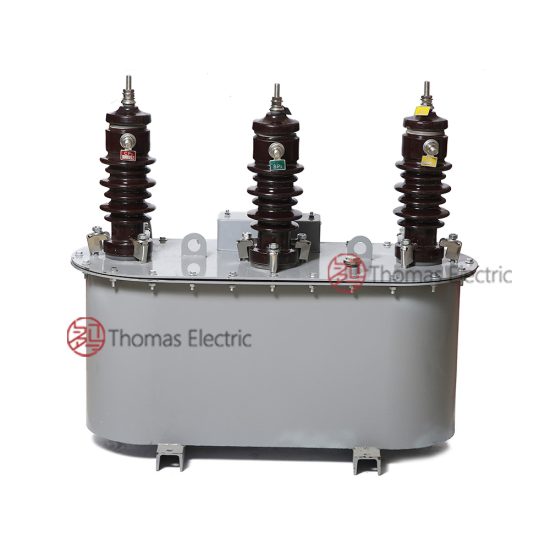
The JLS-20K is a single-phase, indoor/outdoor-rated cast-resin voltage transformer (VT) engineered for precise voltage transformation in medium-voltage networks operating at a nominal system voltage of 20 kV (with an IEC-standard primary voltage rating of 21 kV). Designed in strict accordance with IEC 61869-3 and GB/T 20840.3, this instrument transformer provides reliable isolation and accurate scaling of high primary voltages to standardized secondary outputs—typically 100 V or 110 V—for use in revenue metering, protective relaying, and power quality monitoring systems.
Operating Principle of Cast-Resin Insulation
Cast-resin insulation in the JLS-20K employs vacuum pressure impregnation (VPI) epoxy technology, wherein the entire magnetic core and winding assembly are fully encapsulated in a homogeneous, void-free epoxy matrix under controlled vacuum and pressure conditions. This process eliminates air pockets that could lead to partial discharges under sustained electrical stress. The resulting solid dielectric structure exhibits excellent tracking resistance, hydrophobic surface properties, and superior mechanical rigidity. Unlike oil-filled counterparts, the cast-resin design eliminates fire hazards, environmental contamination risks, and maintenance-intensive oil sampling. The epoxy compound used complies with UL 94 V-0 flammability ratings and maintains stable dielectric strength (>20 kV/mm) across the operational temperature range of –40°C to +40°C ambient.
Advantages Over Oil-Immersed Designs
Compared to traditional oil-immersed VTs, the JLS-20K offers significant operational and safety benefits. Its dry-type construction eliminates the need for oil containment systems, reducing footprint and enabling installation in confined spaces such as indoor switchrooms or urban substations with stringent fire codes. The absence of liquid insulation also removes risks associated with oil leakage, degradation over time, and moisture ingress—common failure modes in oil-filled units. Furthermore, cast-resin VTs exhibit lower thermal time constants, allowing faster response to transient overvoltages without thermal runaway. The JLS-20K’s solid insulation system demonstrates long-term stability under continuous 1.2×Un operation and withstands temporary overvoltages up to 1.9×Un for 8 hours without performance degradation, per IEC 61869-3 Clause 7.4.
Typical Applications Overview
The JLS-20K is deployed across diverse power infrastructure segments where accuracy, reliability, and compliance are non-negotiable. Primary applications include utility-owned distribution substations (20/0.4 kV), industrial plant switchyards, renewable energy interconnection points (e.g., solar farms feeding into 20 kV grids), and railway traction power systems. Its dual secondary windings—one optimized for 0.2 or 0.5 class metering, the other for 3P or 6P class protection—enable simultaneous connection to billing meters and overvoltage/undervoltage relays. The transformer’s robust creepage distance (≥630 mm for pollution degree III) ensures reliable operation in coastal or industrial environments with high salinity or airborne contaminants.
Technical Specifications
The JLS-20K is engineered to meet exacting performance criteria under both international and domestic regulatory frameworks. Below is a comprehensive specification table followed by detailed service condition parameters.
| Parameter | Value |
|---|---|
| Primary Voltage (IEC) | 21 kV |
| System Voltage (Domestic) | 20 kV |
| Secondary Voltages | 100 V / √3, 100 V, or 110 V (configurable) |
| Voltage Ratio | 21,000 / 100 V (standard); custom ratios available |
| Accuracy Class (Metering) | 0.2, 0.5 (per IEC 61869-3 Table 101) |
| Accuracy Class (Protection) | 3P, 6P (composite error ≤3% or ≤6% at rated burden) |
| Rated Output (per winding) | 10–100 VA (standard); up to 150 VA optional |
| Insulation Level (LI/AC) | 170 kV / 70 kV (per IEC 60071-1) |
| Short-Time Thermal Withstand | 1 s at 25×In (secondary short-circuit current) |
| Core Material | Grain-Oriented Electrical Steel (GOES), M4 grade |
| Insulation System | VPI Epoxy Resin, Class F (155°C) |
| Pollution Degree | III (creepage ≥630 mm) |
| Ambient Temperature Range | –40°C to +40°C |
| Maximum Altitude | 1,000 m above sea level (derating required >1,000 m) |
Standard Service Conditions
The JLS-20K is rated for continuous operation under standard service conditions defined in IEC 61869-3 Clause 5. Ambient temperature must not exceed +40°C (24-hour average ≤35°C), with a minimum of –40°C for cold-climate variants. Relative humidity may reach 100% at +25°C, provided condensation does not occur during rapid temperature changes. Installation altitude is limited to 1,000 m; for sites between 1,000–3,000 m, the power frequency withstand voltage must be reduced by 1% per 100 m above 1,000 m. The transformer assumes a symmetrical three-phase system with balanced loading and harmonic distortion ≤5% THD. Operation in DC-biased systems (e.g., near HVDC converters) requires special core design validation.
Electrical Performance Tolerances
Voltage ratio error for metering windings must remain within ±0.2% for 0.2 class and ±0.5% for 0.5 class across 20–100% of rated burden and 80–120% of rated voltage. Phase displacement is limited to ±10 minutes for 0.2 class and ±20 minutes for 0.5 class. Protection windings exhibit composite error ≤3% at 5%–100% of rated voltage and 25–100% of rated burden for 3P class. Burden tolerance is ±10% of declared VA rating. All measurements are performed at 50 Hz ±0.5 Hz. The transformer must maintain these tolerances after exposure to 1.2×Un for 8 hours and 1.5×Un for 30 seconds during type testing.
Typical Applications
The JLS-20K’s dual-winding architecture and robust insulation make it suitable for critical roles across modern power systems.
Substation Secondary Metering
In 20 kV distribution substations, the JLS-20K supplies scaled voltage signals to revenue-class kWh meters, demand recorders, and SCADA RTUs. The 0.2-class secondary winding ensures billing accuracy compliant with national regulatory requirements (e.g., China’s DL/T 448). For example, in a typical 20/0.4 kV urban substation serving commercial loads, two JLS-20K units (connected phase-to-ground) feed a three-phase four-wire metering cabinet. The cast-resin body resists dust accumulation in unventilated meter rooms, while the hermetic seal prevents moisture-induced ratio drift—a common issue with open-frame VTs.
Industrial Power Distribution
Heavy industries such as steel mills, chemical plants, and data centers rely on the JLS-20K for both energy accounting and motor protection schemes. In a 20 kV motor control center (MCC), the VT’s 3P-class winding triggers undervoltage relays during grid sags, preventing motor stalling. Simultaneously, the 0.5-class winding feeds a power quality analyzer monitoring voltage flicker from arc furnaces. The transformer’s high short-circuit withstand capability (25×In for 1 s) protects against damage during downstream faults, ensuring continuity of metering during transient events.
Renewable Energy Integration
Solar photovoltaic (PV) farms connected to 20 kV rural feeders use the JLS-20K to interface inverters with grid protection systems. During anti-islanding tests, the VT accurately replicates grid voltage collapse to trigger inverter disconnect within 2 seconds, per GB/T 19964. The unit’s low capacitive coupling (<50 pF between primary and secondary) minimizes false tripping due to high-frequency switching noise from inverters. Field data from 50 MW PV sites in Xinjiang show zero VT failures over five years despite diurnal temperature swings exceeding 60°C.
Rural and Suburban Distribution Networks
In remote areas with limited maintenance access, the JLS-20K’s maintenance-free design reduces lifecycle costs. Mounted on pole-top switchgear or pad-mounted transformers, it enables remote voltage monitoring via cellular-connected RTUs. The extended creepage distance (630 mm) prevents flashovers during fog or light rain in humid southern provinces. A case study in Guangdong demonstrated 99.98% availability over three years in a network with 85% humidity year-round—outperforming legacy oil-filled VTs that required annual oil testing.
Compliance with International Standards
The JLS-20K is certified to both global and Chinese national standards, ensuring interoperability and regulatory acceptance.
IEC 61869-3 Compliance Details
IEC 61869-3 governs the performance, testing, and marking of inductive voltage transformers. The JLS-20K meets all mandatory clauses, including insulation coordination (Clause 7), accuracy verification (Clause 10), and thermal behavior (Clause 11). Type tests include power frequency withstand (70 kV rms for 1 min), lightning impulse (170 kV peak, 1.2/50 μs waveform), and temperature rise (≤60 K for windings at 1.2×Un). Routine tests cover ratio error, polarity, and insulation resistance (>1,000 MΩ at 2,500 V DC). The transformer bears the CE mark and includes a test report traceable to an ISO/IEC 17025-accredited laboratory.
GB/T 20840.3 Alignment
GB/T 20840.3 is China’s adoption of IEC 61869-3 with minor national deviations. Key differences include stricter partial discharge limits (<10 pC at 1.2×Un/√3 vs. IEC’s <20 pC) and mandatory seismic testing for transformers installed in zones with PGA ≥0.15g. The JLS-20K exceeds both requirements, achieving <8 pC in factory PD tests and passing horizontal/vertical shake tests at 0.3g. Additionally, GB/T 20840.3 mandates dual secondary terminals labeled “a–n” (metering) and “da–dn” (protection)—a feature implemented on all JLS-20K units shipped to Chinese utilities.
Testing and Certification Requirements
Certification involves three test tiers: type tests (performed once per design), routine tests (100% production), and sample tests (per batch). Type tests validate design integrity under extreme conditions, including short-circuit withstand and thermal stability. Routine tests verify ratio error, polarity, and insulation resistance on every unit. Sample tests—conducted quarterly—include partial discharge and temperature rise. All test data is archived for 10 years per CNAS requirements.
On-Site Testing Procedures
Field commissioning of the JLS-20K requires verification of key parameters to ensure safe integration into the power system.
Insulation Resistance Test
Using a 2,500 V DC megohmmeter, measure insulation resistance between primary winding and ground, secondary windings and ground, and primary-to-secondary. Acceptance criteria: ≥1,000 MΩ for new units; ≥500 MΩ for units in service. Measurements must be corrected to 20°C using the formula R20 = Rt × 2(t–20)/10. Low readings indicate moisture ingress or resin cracking—requiring drying or replacement. Perform before and after power frequency withstand tests to detect insulation degradation.
Turns Ratio Test
Apply a low-voltage AC source (50–100 V) to the primary and measure secondary voltage with a calibrated voltmeter. Calculate actual ratio and compare to nameplate. Tolerance: ±0.2% for 0.2-class windings, ±0.5% for 0.5-class. Use a ratio bridge for highest accuracy. Deviations beyond tolerance suggest turn-to-turn shorts or incorrect tap selection. Always de-energize and ground the primary before connecting test leads.
Polarity Test
Verify reducing polarity using the DC kick method: connect a 6–12 V battery to primary (H1+, H2–) and a center-zero galvanometer to secondary (X1, X2). A momentary positive deflection confirms correct polarity. Incorrect polarity causes 180° phase shift, leading to metering errors or relay misoperation. Polarity must match adjacent CTs in three-phase systems to maintain vector group consistency.
Power Frequency Withstand Voltage Test
Apply 70 kV rms at 50 Hz between primary and grounded secondary/core for 1 minute. Use a calibrated test transformer with overcurrent protection set at 10 mA. No flashover or disruptive discharge is permitted. Reduce test voltage by 10% for units in service. Ensure all secondary terminals are shorted and grounded during the test to avoid core saturation.
Open-Circuit Test (for VT)
With secondary open, apply 100% rated voltage to primary and measure no-load current and losses. Compare to factory baseline: no-load current should be ≤0.5% of rated primary current; losses ≤15 W. Significant increases indicate core lamination damage or interlaminar shorts. This test validates magnetic circuit integrity after transport or seismic events.
Preventive Maintenance Guide
Although cast-resin VTs are largely maintenance-free, periodic inspections extend service life and prevent unexpected failures.
Periodic Inspection Protocol
Conduct visual and electrical checks annually. Inspect for surface cracks, tracking marks, or discoloration on the resin housing. Clean terminals with isopropyl alcohol and verify torque on M10 studs (25 N·m). Measure insulation resistance and compare to baseline—declines >20% warrant further investigation. Check secondary wiring for loose connections, which can cause arcing and ratio errors. In coastal areas, rinse housing with deionized water to remove salt deposits.
Maintenance Intervals and Fault Diagnosis
Replace units exhibiting any of the following: insulation resistance <300 MΩ, ratio error exceeding twice the accuracy class limit, or visible resin delamination. Most failures stem from external factors: lightning surges (evidenced by carbon tracking), ferroresonance (causing overheating), or mechanical impact during installation. A 5-year schedule includes thermographic scanning to detect hot spots (>10 K above ambient) and partial discharge measurement if insulation resistance drops below 500 MΩ.
| Interval | Action |
|---|---|
| Annually | Visual inspection, terminal cleaning, insulation resistance test |
| Every 3 Years | Thermographic scan, ratio verification |
| Every 5 Years | Partial discharge test (if indicated), open-circuit test |
| After Major Fault | Full suite of on-site tests per Section 5 |
Conclusion
The JLS-20K 21kV cast-resin voltage transformer represents a convergence of precision engineering, material science, and international standardization. By leveraging VPI epoxy encapsulation and GOES core technology, it delivers exceptional accuracy (0.2/0.5 class for metering, 3P/6P for protection) while eliminating the fire and environmental risks inherent in oil-filled designs. Its compliance with both IEC 61869-3 and GB/T 20840.3 ensures seamless deployment across global markets—from European distribution networks to Chinese smart grids. Field-proven reliability in harsh environments, including high humidity, pollution, and temperature extremes, underscores its robustness. With a design life of 25–30 years under standard service conditions, the JLS-20K minimizes total cost of ownership through zero routine maintenance and high immunity to aging mechanisms like moisture absorption or oil oxidation. As power systems evolve toward greater digitization and distributed generation, this transformer’s stable ratio characteristics and low electromagnetic interference profile make it an indispensable component for accurate energy measurement and dependable system protection. Utilities and industrial operators selecting the JLS-20K gain not only a compliant device but a long-term asset engineered for decades of trouble-free operation.
Q1: Can the JLS-20K be used in 50 Hz and 60 Hz systems?
A1: Yes. The JLS-20K is designed for 50 Hz operation per IEC/GB standards. For 60 Hz applications, core cross-section is adjusted to maintain flux density below 1.6 T—contact manufacturer for 60 Hz variant.
Q2: What is the maximum secondary burden for 0.2-class accuracy?
A2: At 100 V secondary, the burden must not exceed 30 VA for 0.2-class compliance. Higher burdens degrade accuracy—e.g., 50 VA may shift error to ±0.35%.
Q3: Is the JLS-20K suitable for indoor installation only?
A3: No. It is rated for both indoor and outdoor use (IP00 enclosure). For outdoor mounting, install under a drip shield to prevent direct rainfall on terminals.
Q4: How does ferroresonance affect the JLS-20K?
A4: Like all VTs, it is susceptible during single-pole switching on unloaded cables. Mitigation includes installing damping resistors (≥500 Ω) across secondary or using 3-phase VT banks.
Q5: What is the warranty period?
A5: Standard warranty is 5 years against manufacturing defects, extendable to 10 years with registered preventive maintenance records.