Article Content
Introduction
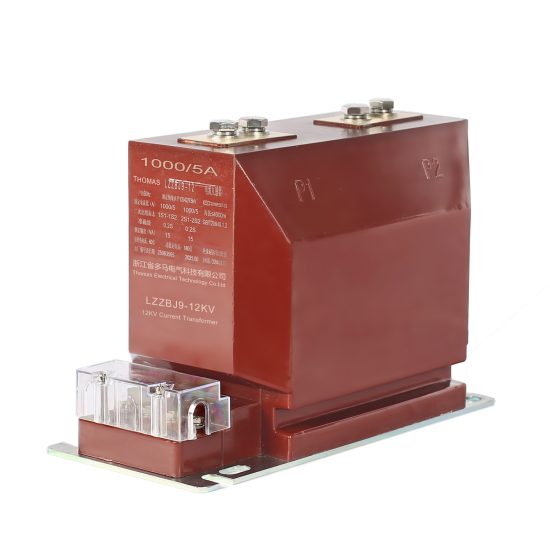
The LZZBJ9-10 current transformer is a widely used indoor-type, resin-cast, through-core instrument transformer designed for 10kV power systems. It serves critical roles in electrical energy metering, protective relaying, and system monitoring by accurately transforming high primary currents into standardized, lower secondary currents suitable for connected instruments and relays. Constructed with high-quality epoxy resin and featuring excellent insulation properties, mechanical strength, and resistance to environmental factors such as humidity and pollution, the LZZBJ9-10 ensures reliable operation under normal and transient conditions. Its compact design facilitates easy installation in switchgear panels, ring main units (RMUs), and other medium-voltage distribution equipment. This selection guide provides essential technical considerations to assist engineers and procurement specialists in correctly specifying the LZZBJ9-10 for their specific application needs, ensuring safety, accuracy, and long-term performance.
System Voltage
Selecting the appropriate LZZBJ9-10 current transformer begins with confirming compatibility with the system voltage. Although designated as a “10kV” device, this rating refers to its nominal system voltage class, not the exact operating voltage. The LZZBJ9-10 is engineered for use in three-phase AC systems with a rated voltage of 10kV (line-to-line), corresponding to a phase-to-ground voltage of approximately 5.77kV. Crucially, the transformer must withstand both continuous operating voltages and transient overvoltages without insulation failure.
The insulation level of the LZZBJ9-10 complies with IEC 61869 and GB/T 20840 standards. Key dielectric test values include a power frequency withstand voltage of 42kV (rms) for 1 minute and a lightning impulse withstand voltage of 75kV (peak). These parameters ensure safe operation even during switching surges or lightning-induced transients common in distribution networks. When integrating the transformer into a system, engineers must verify that the network’s maximum operating voltage—including any anticipated temporary overvoltages—remains within the transformer’s insulation capabilities. Additionally, the system grounding method (e.g., solidly grounded, resistance grounded, or ungrounded) influences the phase-to-ground voltage stress and should be considered during selection. Using a 10kV-class CT in a system rated above 12kV (the upper limit of the 10kV class per IEC 60038) may compromise safety and violate regulatory codes.
| Parameter | Value | Standard Reference |
|---|---|---|
| Rated System Voltage (Ur) | 10 kV (line-to-line) | IEC 60038 |
| Maximum System Voltage (Um) | 12 kV | IEC 60038 |
| Power Frequency Withstand Voltage | 42 kV (1 min) | IEC 61869-3 |
| Lightning Impulse Withstand Voltage | 75 kV (1.2/50 µs) | IEC 61869-3 |
Transformation Ratio
The transformation ratio (also called turns ratio) defines the relationship between the primary current (Ip) and the secondary current (Is) of the current transformer. For the LZZBJ9-10, standard secondary current is 5 A or 1 A, while primary currents typically range from 10 A to 3000 A. The ratio is expressed as Ip:Is (e.g., 400:5 or 600:1). Correct selection of the transformation ratio is vital to ensure that connected instruments operate within their optimal range while maintaining adequate accuracy and protection coordination.
When choosing a ratio, consider both normal load current and potential fault currents. The primary current rating should be equal to or slightly higher than the maximum continuous load current of the circuit. Selecting a ratio too large (e.g., 2000:5 for a 100 A load) results in poor metering accuracy at low loads because the secondary current falls below the instrument’s minimum measurable threshold. Conversely, a ratio too small may saturate the CT core during overloads or short circuits, leading to inaccurate readings or failure of protective relays to operate correctly.
The LZZBJ9-10 often features multiple secondary windings (e.g., one for metering and another for protection), each possibly with different ratios or taps. Some models offer dual-ratio or multi-tap configurations (e.g., 600/1200:5), allowing field adjustment without replacing the unit. The table below lists common transformation ratios available for the LZZBJ9-10 series:
| Primary Current (A) | Secondary Current (A) | Common Ratios | Typical Application |
|---|---|---|---|
| 10 – 100 | 5 or 1 | 50:5, 75:5, 100:1 | Low-load feeders, small transformers |
| 150 – 600 | 5 or 1 | 200:5, 400:5, 600:1 | Main distribution circuits, MV/LV transformers |
| 800 – 1500 | 5 or 1 | 1000:5, 1200:5, 1500:1 | Industrial feeders, large motors |
| 2000 – 3000 | 5 or 1 | 2000:5, 2500:5, 3000:1 | Substation incomers, high-capacity lines |
Designers must also account for future load growth. Specifying a ratio with some headroom (e.g., 20–30% above expected max load) enhances system flexibility. However, excessive headroom degrades metering performance. Always consult the manufacturer’s datasheet for exact available ratios and confirm thermal and dynamic current ratings align with system short-circuit levels.
Accuracy Class
Accuracy class defines the permissible error limits of a current transformer under specified operating conditions. The LZZBJ9-10 is available in multiple accuracy classes tailored for either metering (revenue or monitoring) or protection functions. Understanding these classes is essential to ensure compliance with regulatory requirements and proper system functionality.
For metering applications, common accuracy classes include 0.2, 0.5, and 1.0. These numbers represent the maximum composite error (in percent) at the rated primary current and burden. For instance, a 0.5-class CT will not exceed ±0.5% current error and ±15 minutes phase displacement at 100% rated current and specified burden. Class 0.2S or 0.5S denotes “special” accuracy, optimized for wide-range metering (e.g., from 1% to 120% of rated current), making them ideal for revenue metering where precision across varying loads is critical.
Protection-class CTs are designated with suffixes like 5P or 10P (e.g., 5P10, 10P20). The number before “P” indicates the maximum permissible composite error (5% or 10%) under specified conditions, while the number after denotes the accuracy limit factor (ALF)—the multiple of rated primary current up to which the error remains within limits. For example, a 10P20 CT maintains ≤10% error up to 20 times the rated primary current, which is crucial during fault conditions when relays must operate reliably.
| Accuracy Class | Max Current Error (%) | Phase Displacement (minutes) | Application |
|---|---|---|---|
| 0.2 / 0.2S | ±0.2 | ±10 | Precision metering, revenue billing |
| 0.5 / 0.5S | ±0.5 | ±15 | General metering, sub-billing |
| 1.0 | ±1.0 | ±30 | Monitoring, non-critical metering |
| 5P10 | ±5 at 10× In | Not specified | Overcurrent protection |
| 10P20 | ±10 at 20× In | Not specified | Backup protection, high fault levels |
When selecting an accuracy class, match it precisely to the connected device’s requirements. Using a protection-class CT for metering may result in significant errors at normal load currents, while a high-accuracy metering CT may saturate during faults, failing to drive protective relays. Additionally, the specified burden (in VA) must be compatible with the actual connected load; exceeding the rated burden degrades accuracy. Always verify the complete specification—including class, burden, and ALF—with system study data.
5. Burden Calculation
The burden of a current transformer (CT) is the total impedance presented to its secondary winding, comprising connected devices (relays, meters, leads) and wiring. Accurate burden calculation ensures the CT operates within its accuracy class and avoids saturation under normal or fault conditions.
Burden is typically expressed in volt-amperes (VA) at a specified secondary current (usually 1 A or 5 A). The total burden \( Z_b \) is calculated as:
\[
Z_b = Z_{\text{relay}} + Z_{\text{leads}} + Z_{\text{connections}}
\]
Where:
- \( Z_{\text{relay}} \): Impedance of protective relays or metering devices
- \( Z_{\text{leads}} \): Total impedance of secondary wiring (round-trip)
- \( Z_{\text{connections}} \): Contact resistance at terminals (often negligible but included for precision)
Lead impedance depends on conductor length, cross-sectional area, and material resistivity. For copper conductors at 20°C:
\[
R_{\text{lead}} = \frac{\rho \cdot L}{A}
\]
Where \( \rho = 0.01724 \, \Omega \cdot \text{mm}^2/\text{m} \), \( L \) is one-way length (m), and \( A \) is cross-section (mm²). Total lead impedance is doubled for round-trip.
| Component | Typical Impedance (Ω) | Notes |
|---|---|---|
| Electromechanical Relay | 0.1 – 0.5 | Higher for older designs |
| Numerical Relay | 0.01 – 0.05 | Low burden due to electronic input |
| Meter (Analog) | 0.1 – 0.3 | Depends on type and rating |
| 10 m Lead (2.5 mm² Cu, 5 A) | 0.138 | Round-trip: \( 2 \times (0.01724 \times 10 / 2.5) \) |
| Terminal Connections | 0.01 – 0.02 | Assumed clean and tight |
Example: A 5 A CT feeds a numerical relay (0.02 Ω) via 30 m of 4 mm² copper cable. Total burden:
- Lead resistance: \( 2 \times (0.01724 \times 30 / 4) = 0.259 \, \Omega \)
- Total \( Z_b = 0.02 + 0.259 + 0.015 \approx 0.294 \, \Omega \)
- Burden in VA: \( I^2 Z = 5^2 \times 0.294 = 7.35 \, \text{VA} \)
This must be less than the CT’s rated burden (e.g., 10 VA or 15 VA) to maintain accuracy.
6. Short-Circuit Performance
Current transformers must withstand high short-circuit currents without mechanical damage or loss of insulation integrity. More critically, they must avoid saturation during fault conditions to ensure protective relays receive accurate current representation for correct operation.
Short-circuit performance is evaluated using the CT’s knee-point voltage (\( V_k \)) and symmetrical short-circuit current (\( I_{sc} \)). The CT ratio error remains acceptable only if the secondary voltage during a fault does not exceed \( V_k \).
The required knee-point voltage is estimated by:
\[
V_k \geq I_{f(sec)} \cdot (Z_b + Z_{ct})
\]
Where:
- \( I_{f(sec)} \): Secondary fault current (primary fault current divided by CT ratio)
- \( Z_b \): Total external burden
- \( Z_{ct} \): CT internal secondary winding impedance
Standards such as IEC 61869-2 define accuracy limit factor (ALF), which is the ratio of maximum fault current to rated current that the CT can handle within specified error limits. For example, a 5P20 CT maintains ≤5% error up to 20× rated current.
| Parameter | Description | Typical Value/Range |
|---|---|---|
| Knee-Point Voltage (\( V_k \)) | Voltage at which core begins to saturate | 50 V – 500 V (depends on design) |
| Accuracy Limit Factor (ALF) | Max multiple of rated current for accuracy | 5, 10, 15, 20, 30 |
| Thermal Short-Time Current | Max RMS current for 1–3 seconds without damage | 20–100 kA (system-dependent) |
| Dynamic Withstand Current | Peak current for mechanical integrity | ≈2.5 × thermal rating |
Designers must verify that the CT’s ALF exceeds the actual fault-to-rated current ratio. If not, a higher-class CT (e.g., 5P20 instead of 5P10) or lower burden wiring must be used. Saturation causes distorted secondary current, potentially delaying or blocking relay tripping—especially critical for differential and distance protection schemes.
7. Environmental Considerations
Environmental factors significantly influence CT selection, installation, and long-term reliability. These include temperature extremes, humidity, altitude, pollution, and exposure to chemicals or salt spray.
Ambient Temperature: Standard CTs operate between –25°C and +55°C. Outside this range, derating or special insulation (e.g., silicone rubber) may be required. High temperatures accelerate insulation aging; low temperatures can embrittle materials.
Altitude: Above 1000 m, air density decreases, reducing dielectric strength and cooling efficiency. IEC 60076-11 recommends derating: for every 100 m above 1000 m, reduce rated voltage by 1.2% or use altitude-corrected designs.
Pollution and Humidity: In coastal or industrial areas, conductive dust, salt, or chemical vapors can cause surface tracking or corrosion. CTs should have appropriate IP ratings (e.g., IP54 minimum for outdoor use) and creepage distances per pollution degree (IEC 60664-1).
Seismic Conditions: In earthquake-prone zones, CTs must meet seismic withstand requirements (e.g., IEEE 693 or IEC 60068-2-57), often requiring reinforced mounting and reduced center of gravity.
| Environmental Factor | Impact on CT | Mitigation Strategy |
|---|---|---|
| High Humidity / Condensation | Insulation degradation, flashover | Hermetic sealing, hydrophobic coatings, heaters |
| Coastal (Salt Spray) | Corrosion of terminals/housing | Stainless steel hardware, epoxy resin encapsulation |
| Industrial Pollution | Surface leakage currents | Increased creepage distance, silicone sheds |
| High Altitude (>1000 m) | Reduced dielectric strength | Derating, pressurized or SF6-filled units |
| Extreme Cold (<–25°C) | Brittle insulation, oil solidification | Low-temp compounds, dry-type CTs |
Always consult manufacturer data sheets for environmental ratings and ensure compliance with local codes (e.g., NEC, IEC, IEEE). Outdoor CTs should feature UV-resistant housings and drainage to prevent water accumulation.
8. CT Selection and Verification Checklist
Use this checklist during design, procurement, and commissioning to ensure CT suitability and system reliability:
| # | Check Item | Verified? (Y/N) |
|---|---|---|
| 1 | Primary current rating matches max load and fault levels | |
| 2 | Secondary current (1 A or 5 A) compatible with relays/meters | |
| 3 | Accuracy class meets application (e.g., 0.5 for metering, 5P for protection) | |
| 4 | Calculated total burden ≤ CT rated burden | |
| 5 | ALF ≥ (Max fault current / Rated primary current) | |
| 6 | Knee-point voltage sufficient for worst-case fault scenario | |
| 7 | Thermal and dynamic short-circuit ratings exceed system values | |
| 8 | Environmental rating suitable for location (IP, temp, altitude, etc.) | |
| 9 | Physical dimensions and mounting compatible with switchgear/busbar | |
| 10 | Secondary wiring uses adequate conductor size to minimize burden | |
| 11 | CT polarity marked correctly and verified during testing | |
| 12 | Open-circuit protection (e.g., shorting switches) provided for maintenance |
Final verification should include site acceptance tests: insulation resistance, winding resistance, polarity check, excitation curve (to confirm \( V_k \)), and ratio test. Never energize a CT with an open secondary circuit—it can generate lethal voltages and damage the core.