Article Content
Introduction
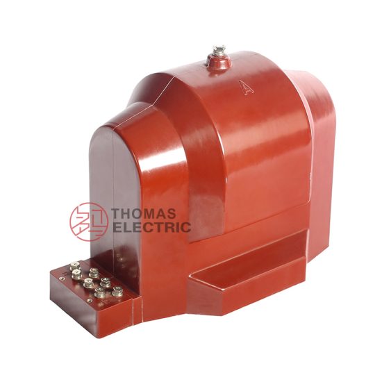
The JDZ9-10 voltage transformer is a critical component in medium-voltage power systems, specifically engineered for accurate voltage measurement and reliable protection in 10 kV networks. As a resin-insulated, indoor-type instrument transformer, the JDZ9-10 offers high dielectric strength, excellent thermal stability, and long-term operational reliability under varying load conditions. Its compact design and robust construction make it suitable for installation in switchgear panels, substations, and industrial power distribution systems where space efficiency and safety are paramount. This selection guide provides essential technical considerations to assist engineers and system designers in correctly specifying and integrating the JDZ9-10 into their electrical infrastructure. Understanding key parameters such as system voltage compatibility, transformation ratio options, and accuracy class requirements ensures optimal performance, regulatory compliance, and seamless interoperability with metering, protection, and monitoring devices.
System Voltage
The JDZ9-10 voltage transformer is designed explicitly for use in three-phase AC power systems with a nominal system voltage of 10 kV. However, it is crucial to distinguish between nominal system voltage, maximum operating voltage, and insulation level when selecting this device. The “10” in JDZ9-10 refers to the highest RMS line-to-line voltage for which the transformer is rated—specifically, 10 kV. In practice, many 10 kV distribution networks operate at slightly elevated voltages (e.g., 10.5 kV or 11 kV) during light-load conditions due to regulation practices. The JDZ9-10 is typically rated for a maximum system voltage of 12 kV, aligning with IEC 61869 standards for instrument transformers in this voltage class.
Proper matching of the transformer’s voltage rating to the actual system parameters ensures both safety and measurement fidelity. Overvoltage conditions beyond the rated insulation level can lead to partial discharge, insulation degradation, or catastrophic failure. Conversely, undersizing may result in inaccurate secondary output or inadequate coordination with protective relays. The primary winding must be connected phase-to-ground in most applications, meaning the transformer experiences a phase voltage of approximately 5.77 kV (i.e., 10 kV / √3) under balanced conditions. Therefore, the insulation system of the JDZ9-10 is tested to withstand both power frequency and lightning impulse voltages consistent with a 10/12 kV system.
| Parameter | Value | Standard Reference |
|---|---|---|
| Nominal System Voltage (Un) | 10 kV | IEC 60038 |
| Maximum System Voltage (Um) | 12 kV | IEC 61869-3 |
| Power Frequency Withstand Voltage (1 min) | 42 kV (primary to ground) | IEC 61869-3 |
| Lightning Impulse Withstand Voltage | 75 kV (peak) | IEC 61869-3 |
| Typical Connection | Phase-to-ground (single-phase unit) | Application Practice |
Transformation Ratio
The transformation ratio of a voltage transformer defines the relationship between the primary (high-voltage) and secondary (low-voltage) windings. For the JDZ9-10, this ratio is standardized to ensure compatibility with common metering and protection equipment that typically operates on 100 V or 100/√3 V secondary signals. The most prevalent ratio for this model is 10,000 V / 100 V (or 100:1), though variants such as 10,000 V / (100/√3) V are also available for systems requiring phase-to-neutral secondary outputs. The choice of ratio directly impacts the scaling of voltage measurements and must align with the system configuration—whether it is a three-phase three-wire (delta) or three-phase four-wire (wye) network.
In a wye-connected system, each JDZ9-10 unit is connected between one phase and ground. Here, the primary voltage per unit is the phase voltage (10 kV / √3 ≈ 5,774 V). To produce a standard secondary phase voltage of 100/√3 V (≈57.7 V), the required transformation ratio becomes (10,000/√3) : (100/√3), which simplifies to 100:1. Thus, even in grounded wye systems, the nominal ratio is still expressed as 10,000/100 V for simplicity and catalog standardization. It is essential to verify whether the secondary output is specified as line-to-line (100 V) or phase-to-neutral (100/√3 V) when interfacing with meters or relays.
Multi-ratio versions of the JDZ9-10 are occasionally offered, featuring tapped secondary windings that allow selection among ratios like 10,000/100 V, 10,000/110 V, or others. These provide flexibility during system upgrades or in export markets with differing secondary standards. However, changing taps affects both the voltage factor and the burden capability; thus, any deviation from the standard ratio must be validated against the connected device’s input requirements and the transformer’s rated output (typically 30 VA, 50 VA, or 100 VA).
Incorrect ratio selection leads to systematic errors in energy billing, improper relay operation, or false alarms in monitoring systems. For example, using a 10,000/100 V transformer in a system expecting 10,000/(100/√3) V will cause all phase voltage readings to appear √3 times higher than actual, potentially triggering overvoltage protections unnecessarily. Always confirm the secondary voltage expectation of downstream equipment before finalizing the ratio.
| Primary Voltage (V) | Secondary Voltage (V) | Common Application | System Type |
|---|---|---|---|
| 10,000 | 100 | Line-to-line measurement in delta or ungrounded systems | 3-phase, 3-wire |
| 10,000 / √3 (≈5,774) | 100 / √3 (≈57.7) | Phase-to-neutral measurement in grounded wye systems | 3-phase, 4-wire |
| 10,000 | 110 | Legacy or regional metering standards (e.g., some Asian markets) | Varies |
| 10,000 | Multiple taps (e.g., 100/110) | Flexible deployment or retrofit projects | Custom |
Note: Although the primary is rated for 10 kV line-to-line, the physical winding is designed for phase voltage in grounded applications. The ratio label “10,000/100” is a nominal designation; actual turns ratio corresponds to the phase voltages in wye systems.
Accuracy Class
Accuracy class defines the permissible error limits in voltage transformation under specified operating conditions, including burden and power factor. For the JDZ9-10 voltage transformer, accuracy classes are designated according to international standards such as IEC 61869-3, with common classes including 0.2, 0.5, 1, and 3. These numbers represent the maximum permissible composite error (in percent) at the rated burden and within 80–120% of rated voltage. For instance, a class 0.5 transformer must maintain voltage measurement error within ±0.5% under defined test conditions.
Selection of the appropriate accuracy class depends entirely on the application:
- Class 0.2 or 0.5: Used for precision revenue metering, tariff calculations, and high-accuracy monitoring where even small errors translate to significant financial discrepancies over time.
- Class 1: Suitable for general-purpose metering, substation monitoring, and basic control functions where moderate accuracy suffices.
- Class 3: Typically reserved for protection applications (e.g., overvoltage or undervoltage relaying), where exact voltage magnitude is less critical than reliable detection of abnormal conditions.
It is vital to note that accuracy is only guaranteed when the connected burden (expressed in volt-amperes, VA) does not exceed the transformer’s rated output and matches the power factor assumed during calibration (usually 0.8 lagging for metering classes). Exceeding the burden degrades accuracy and may shift the operating point outside the certified class. The JDZ9-10 is commonly available with rated outputs of 30 VA, 50 VA, or 100 VA, and the chosen accuracy class applies only up to that specific burden.
| Accuracy Class | Max. Voltage Error (%) | Phase Displacement (minutes) | Typical Applications | Min. Rated Burden (VA) |
|---|---|---|---|---|
| 0.2 | ±0.2 | ≤10 | Revenue metering, calibration labs | 30 |
| 0.5 | ±0.5 | ≤20 | Commercial/industrial billing | 30 |
| 1 | ±1.0 | ≤40 | General monitoring, SCADA | 25 |
| 3 | ±3.0 | Not specified | Protective relaying | 15 |
Manufacturers often specify dual accuracy classes (e.g., “0.5/3”) for a single unit, indicating that the transformer meets class 0.5 for metering burdens and class 3 for protection burdens. When selecting a JDZ9-10, always verify that the declared accuracy class aligns with both the intended function and the actual connected load. Misapplication—such as using a class 3 unit for billing—can violate regulatory requirements and compromise system integrity.
5. Burden Calculation
The burden of a current transformer (CT) is the total impedance presented to its secondary winding, comprising the connected devices (relays, meters, etc.) and the wiring between them. Accurate burden calculation is essential to ensure the CT operates within its accuracy class and does not saturate under normal or fault conditions.
Burden is typically expressed in volt-amperes (VA) at a specified secondary current (usually 1 A or 5 A). The total burden \( Z_b \) is calculated as:
\[
Z_b = Z_{\text{lead}} + Z_{\text{device}}
\]
Where:
- \( Z_{\text{lead}} \) = Impedance of the connecting leads
- \( Z_{\text{device}} \) = Impedance of the connected metering or protection device(s)
The lead impedance depends on wire length, cross-sectional area, and material resistivity. For copper conductors at 20°C:
\[
R = \frac{\rho \cdot L}{A}
\]
Where \( \rho = 0.0178 \, \Omega \cdot \text{mm}^2/\text{m} \), \( L \) is the total loop length (go and return), and \( A \) is the conductor cross-section in mm².
| Conductor Size (mm²) | Resistance per km (Ω/km) | Typical Max Lead Length for 5 A System (m) | Max Allowable Burden (VA) at 5 A |
|---|---|---|---|
| 2.5 | 7.4 | 30 | 5.6 |
| 4.0 | 4.6 | 50 | 5.8 |
| 6.0 | 3.1 | 75 | 5.9 |
| 10.0 | 1.8 | 120 | 6.0 |
Designers must ensure that the total calculated burden does not exceed the CT’s rated burden (e.g., 5 VA, 10 VA, or 15 VA). Exceeding this value can cause ratio errors, phase shift, and potential misoperation of protective relays. For digital relays with low input impedance (typically <0.1 Ω), burden is often dominated by lead resistance. Always verify burden during commissioning using secondary injection tests.
6. Short-Circuit Considerations
Current transformers must withstand high short-circuit currents without mechanical damage or loss of performance. During system faults, primary currents can reach 20–100 times the nominal rating for durations of 0.1 to 3 seconds. CTs are rated for two key short-circuit parameters: thermal withstand current (\( I_{th} \)) and dynamic (or peak) withstand current (\( I_{dyn} \)).
The thermal withstand rating defines the RMS current the CT can carry for 1 second without exceeding temperature limits. It is typically expressed as a multiple of the rated primary current (e.g., 40 × In). The dynamic withstand current represents the peak electrodynamic force the CT can endure, usually 2.5 times the thermal rating due to the asymmetrical nature of fault currents.
| CT Rating (Primary Current) | Thermal Withstand (Ith) | Dynamic Withstand (Idyn) | Test Duration | Standard Reference |
|---|---|---|---|---|
| 100/5 A | 4 kA (40 × In) | 10 kA | 1 s | IEC 61869-2 |
| 600/1 A | 30 kA (50 × In) | 75 kA | 1 s | IEEE C57.13 |
| 1200/5 A | 50 kA (41.7 × In) | 125 kA | 1 s | IEC 61869-2 |
Failure to meet short-circuit ratings can result in insulation breakdown, core deformation, or terminal damage. Additionally, CT saturation during high-magnitude faults may distort secondary current waveforms, leading to delayed or failed relay operation. To mitigate this, use CTs with appropriate accuracy limit factor (ALF) or consider high-saturation cores (e.g., class PX or TPX for protection applications). Always coordinate CT short-circuit ratings with the prospective fault level at the installation point.
7. Environmental Factors
Environmental conditions significantly influence CT selection, performance, and longevity. Key factors include ambient temperature, humidity, altitude, pollution levels, and exposure to chemicals or salt spray.
Standard CTs are rated for operation between –5°C and +40°C. For extreme climates (e.g., arctic or desert installations), extended temperature ranges (–40°C to +55°C) may be required, necessitating special materials for insulation and sealing. At altitudes above 1000 m, air density decreases, reducing dielectric strength; thus, CTs installed above this elevation require derating or enhanced insulation clearance.
In coastal or industrial areas, contamination from salt, dust, or chemical vapors can degrade external insulation and promote tracking. In such cases, CTs should have a creepage distance compliant with pollution degree classifications (e.g., ≥25 mm/kV for heavy pollution per IEC 60815). Outdoor CTs must also meet IP (Ingress Protection) ratings—typically IP55 or higher—to prevent water and dust ingress.
| Environment Type | Recommended IP Rating | Creepage Distance (mm/kV) | Special Requirements |
|---|---|---|---|
| Indoor, clean | IP20 | 16–20 | Standard epoxy resin |
| Outdoor, temperate | IP54 | 20–25 | UV-resistant housing |
| Coastal/industrial | IP55 or IP65 | 25–31 | Silicone rubber sheds, anti-corrosion terminals |
| High altitude (>2000 m) | IP54 | 25+ | Dielectric derating or pressurized design |
Additionally, seismic activity in earthquake-prone zones requires CTs with mechanical robustness certified to standards like IEEE 693 or IEC 60068-2-57. Always consult site-specific environmental data during the specification phase to avoid premature failure or safety hazards.
8. Commissioning and Maintenance Checklist
A systematic checklist ensures safe and reliable CT installation, verification, and ongoing operation. This list should be used during commissioning and periodic maintenance.
| # | Check Item | Verification Method | Acceptable Result |
|---|---|---|---|
| 1 | Correct CT ratio and class | Visual inspection & nameplate check | Matches single-line diagram and relay settings |
| 2 | Secondary wiring polarity | Polarity test (kick test or DC method) | Marked P1/S1 ends aligned correctly |
| 3 | Insulation resistance | Megger test (1000 V DC) | >100 MΩ (primary to secondary & ground) |
| 4 | Winding resistance | Low-resistance ohmmeter | Within ±10% of factory values |
| 5 | Burden verification | Measure loop impedance | Total burden ≤ CT rated burden |
| 6 | Secondary circuit grounding | Continuity test | Single-point grounding at CT or panel |
| 7 | No open secondary circuit | Visual & continuity check | All secondaries terminated or shorted |
| 8 | Relay pickup test | Secondary injection | Relay operates at expected current |
Never energize a CT with an open secondary circuit—it can generate lethal voltages (>1000 V) and cause core saturation or insulation failure. Always de-energize the primary circuit before performing maintenance. Retain all test records for future reference and regulatory compliance.