Article Content
Introduction
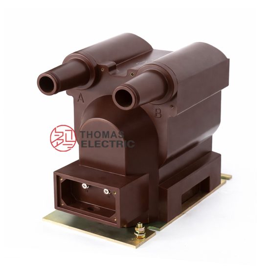
The JDZW-10R voltage transformer is a critical component in medium-voltage power systems, specifically engineered for accurate voltage measurement and reliable operation in 10kV networks. As a resin-insulated, outdoor-type instrument transformer, it provides isolation between high-voltage primary circuits and low-voltage secondary instrumentation, ensuring both safety and precision. This selection guide serves as a technical reference for engineers, system designers, and procurement specialists involved in specifying or installing voltage transformers in distribution substations, industrial facilities, and renewable energy integration projects. The JDZW-10R conforms to international standards such as IEC 61869 and GB/T 20840, guaranteeing performance consistency, thermal stability, and long-term reliability under varying electrical and environmental conditions. Its robust epoxy resin encapsulation offers excellent resistance to moisture, pollution, and UV exposure—making it particularly suitable for harsh outdoor environments. Beyond its role in metering, the JDZW-10R supports protective relaying functions by delivering scaled-down, phase-accurate secondary voltages proportional to the primary system voltage. Proper selection of this device requires careful consideration of system parameters including nominal voltage, transformation ratio, accuracy class, burden rating, and installation environment. This guide addresses these key factors in detail to facilitate optimal performance, regulatory compliance, and operational safety.
System Voltage
Selecting the appropriate JDZW-10R voltage transformer begins with verifying compatibility with the system’s nominal and maximum operating voltages. The “10” in JDZW-10R denotes a rated primary voltage of 10 kV (line-to-line), which corresponds to standard medium-voltage distribution networks. However, actual system voltages may vary due to load fluctuations, regulation practices, or grid topology. Therefore, the transformer must be rated for the highest expected continuous system voltage to avoid insulation stress or measurement errors.
The JDZW-10R is designed for use in systems with a highest voltage for equipment (Um) of 12 kV, as defined by IEC 60038. This ensures safe operation even during transient overvoltages or light-load conditions where system voltage may rise slightly above nominal. The transformer’s insulation level complies with standard short-duration power frequency withstand voltage (28 kV RMS for 1 minute) and lightning impulse withstand voltage (75 kV peak), providing adequate margin for typical distribution system surges.
It is essential to distinguish between line-to-line (L-L) and line-to-earth (L-E) configurations. In a three-phase, three-wire system, the JDZW-10R is typically connected phase-to-ground, requiring a primary voltage rating of Un/√3 = 10 kV / √3 ≈ 5.77 kV per unit. However, the model designation “JDZW-10R” assumes a 10 kV L-L system with phase-to-ground connection, and its internal design accommodates this standard configuration. Misapplication—such as using it in an ungrounded system without proper derating or in a 20 kV network—can lead to insulation failure or inaccurate readings.
The table below summarizes key system voltage parameters relevant to JDZW-10R selection:
| Parameter | Symbol | Value | Standard Reference |
|---|---|---|---|
| Rated Primary Voltage (L-L) | Upn | 10 kV | IEC 61869-3 |
| Highest System Voltage for Equipment | Um | 12 kV | IEC 60038 |
| Power Frequency Withstand Voltage (1 min) | — | 28 kV RMS | GB/T 20840.3 |
| Lightning Impulse Withstand Voltage | — | 75 kV peak | IEC 60060-1 |
| Typical System Configuration | — | 3-phase, effectively grounded or resonant-grounded | — |
Transformation Ratio
The transformation ratio of a voltage transformer defines the relationship between its primary and secondary voltages and is fundamental to accurate metering and protection. For the JDZW-10R, the standard transformation ratio is expressed as 10,000 V / √3 : 100 V / √3, which simplifies to approximately 5774 V : 57.7 V per phase when connected line-to-ground in a 10 kV three-phase system. This ratio ensures that the secondary output remains compatible with standard measuring instruments and protective relays, which typically operate at 100 V (L-L) or 57.7 V (L-N).
However, the JDZW-10R may also be available with alternative secondary voltages such as 110 V or 100/3 V (≈33.3 V), depending on regional standards or specific application requirements. For instance, some legacy systems or export markets may require 110 V secondary outputs. It is crucial to confirm the exact ratio during procurement, as mismatched ratios can cause significant metering errors or relay misoperation.
The transformation ratio is not merely a mathematical scaling factor; it directly influences the transformer’s magnetic design, core saturation characteristics, and burden compatibility. A higher ratio (e.g., 10 kV:100 V) demands a larger number of secondary turns, which increases winding resistance and affects voltage drop under load. Conversely, a lower secondary voltage reduces insulation stress but may compromise signal-to-noise ratio in sensitive applications.
Moreover, the JDZW-10R often features **multiple secondary windings** to serve dual purposes—for example, one winding dedicated to revenue metering (Class 0.2 or 0.5) and another for protection (Class 3P or 6P). Each winding may have the same or different transformation ratios, though in most standard models they share the same primary-to-secondary ratio. When multiple secondaries are present, their combined burden must not exceed the transformer’s rated thermal and accuracy limits.
Below is a representative table of common transformation ratio options for the JDZW-10R series:
| Primary Voltage (L-N) | Secondary Voltage Options | Transformation Ratio (Approx.) | Typical Application |
|---|---|---|---|
| 5774 V (10 kV / √3) | 57.7 V | 100:1 | Standard IEC metering & protection |
| 5774 V | 100 V | 57.74:1 | Legacy systems, some industrial controls |
| 5774 V | 33.3 V (100/3 V) | 173.2:1 | Ground-fault detection in resistor-grounded systems |
| 5774 V | Dual: 57.7 V + 57.7 V | 100:1 (each) | Separate metering and protection circuits |
| 5774 V | Dual: 57.7 V + 33.3 V | 100:1 & 173.2:1 | Combined metering and neutral voltage monitoring |
When selecting the transformation ratio, engineers must also consider the **burden impedance** of connected devices. A mismatch between the transformer’s rated burden (e.g., 30 VA, 50 VA) and the actual load can shift the operating point on the excitation curve, leading to ratio and phase angle errors—especially near the accuracy limit. Always verify that the total connected burden (including wiring resistance) falls within the specified range for the chosen accuracy class.
Accuracy Class
Accuracy class defines the permissible limits of ratio error and phase displacement under specified operating conditions, and it is a decisive factor in determining the suitability of the JDZW-10R for metering or protection applications. The accuracy class is standardized under IEC 61869-3 and GB/T 20840.3, with distinct requirements for measurement (e.g., Class 0.2, 0.5) and protection (e.g., Class 3P, 6P) purposes.
For **revenue metering**, high accuracy is essential to ensure billing integrity. The JDZW-10R is commonly available in Class 0.2 or Class 0.5. Class 0.2 permits a maximum ratio error of ±0.2% and a phase error of ±10 minutes at 100% rated voltage and burden, while Class 0.5 allows ±0.5% ratio error and ±20 minutes phase error. These classes are valid only within a defined voltage range (typically 80–120% of rated voltage) and burden range (25–100% of rated VA). Operating outside these ranges degrades accuracy significantly.
In contrast, **protection applications** prioritize performance during fault conditions—specifically, maintaining reasonable accuracy at elevated voltages (up to 190% of rated) to ensure correct relay operation. Protection-class windings (e.g., 3P or 6P) allow larger errors under normal conditions but guarantee that ratio error does not exceed ±3% (for 3P) or ±6% (for 6P) at rated voltage and up to 190% during overvoltage events. Phase error limits are less stringent, as many protective relays are amplitude-sensitive rather than phase-sensitive.
It is critical to note that a single JDZW-10R unit may house windings of different accuracy classes. For example, one secondary might be Class 0.5 for metering, while another is Class 3P for overvoltage protection. Each winding must be connected only to loads matching its designated purpose and burden rating. Mixing applications can compromise both measurement fidelity and protection reliability.
The table below outlines the accuracy specifications for common classes applicable to the JDZW-10R:
| Accuracy Class | Application | Ratio Error Limit (%) | Phase Error Limit (minutes) | Voltage Range | Burden Range |
|---|---|---|---|---|---|
| 0.2 | Precision metering | ±0.2 | ±10 | 80–120% Un | 25–100% rated VA |
| 0.5 | General metering | ±0.5 | ±20 | 80–120% Un | 25–100% rated VA |
| 1 | Indicating instruments | ±1.0 | ±40 | 80–120% Un | 25–100% rated VA |
| 3P | Protection | ±3.0 | Not specified (typically <120′) | Up to 190% Un | 25–100% rated VA |
| 6P | Protection (less critical) | ±6.0 | Not specified | Up to 190% Un | 25–100% rated VA |
Selecting the correct accuracy class involves balancing cost, regulatory requirements, and functional needs. Over-specifying (e.g., using Class 0.2 for non-revenue monitoring) increases cost unnecessarily, while under-specifying risks non-compliance or system malfunction. Always consult local utility regulations and project specifications before finalizing the accuracy class for your JDZW-10R installation.
5. Burden Calculation
The burden of a current transformer (CT) is the total impedance connected to its secondary winding, typically expressed in volt-amperes (VA) at a specified power factor. Accurate burden calculation is essential to ensure that the CT operates within its accuracy class and delivers reliable measurements or protection signals.
Burden includes the impedance of connected devices (relays, meters, etc.), wiring resistance, and contact resistances. The total burden must not exceed the CT’s rated burden; otherwise, the CT may saturate, leading to inaccurate output during normal or fault conditions.
| Component | Typical Impedance (Ω) | Notes |
|---|---|---|
| Electromechanical Relay | 0.1 – 0.5 | Depends on relay type and coil design |
| Digital Relay | 0.01 – 0.05 | Low burden due to high-input impedance electronics |
| Analog Meter | 0.2 – 1.0 | Higher burden than digital devices |
| Wiring (per 100 ft, 12 AWG) | 0.16 | Resistance increases with length and smaller conductor size |
| Connection Contacts | 0.01 – 0.05 | Assumes clean, tight connections |
To calculate total burden:
- Sum all individual impedances (resistive and reactive components if available).
- Convert to VA using: \( \text{Burden (VA)} = I_s^2 \times Z_b \), where \( I_s \) is the secondary current (typically 1 A or 5 A) and \( Z_b \) is the total burden impedance.
- Compare against the CT’s rated burden (e.g., 10 VA, 15 VA, 30 VA).
For example, with a 5 A secondary CT, 0.3 Ω total burden: \( \text{VA} = 5^2 \times 0.3 = 7.5 \, \text{VA} \). If the CT is rated for 10 VA, this is acceptable. However, under fault conditions, increased current can cause voltage rise across the burden, potentially driving the CT into saturation if the excitation voltage exceeds knee-point voltage.
6. Short-Circuit Considerations
During short-circuit events, CTs must accurately reproduce primary fault currents to enable protective relays to operate correctly. This requires the CT to remain linear (unsaturated) throughout the duration of the fault.
The key parameter is the CT’s ability to handle high overcurrents without saturation, determined by its accuracy limit factor (ALF) or instrument security factor (ISF). For protection-class CTs (e.g., 5P10, 10P20), the number indicates the multiple of rated current up to which the CT maintains specified accuracy.
| CT Class | Max Fault Current (× Rated) | Max Composite Error | Typical Application |
|---|---|---|---|
| 5P10 | 10 | ±5% | Overcurrent protection |
| 10P20 | 20 | ±10% | General protection |
| TPX | Varies | Defined transient error | High-speed differential protection |
| TPY | Varies | Limited remanence | Circuit-breaker failure schemes |
Designers must verify that the maximum expected fault current (including DC offset) does not exceed the CT’s ALF multiplied by its rated current. Additionally, the secondary voltage during a fault (\( V_s = I_s \times Z_b \)) must remain below the CT’s knee-point voltage to avoid saturation.
Transient performance is critical in systems with high X/R ratios, where DC offset can significantly increase the total fault current magnitude. In such cases, special transient-performance CTs (e.g., TP classes per IEC 60044-6) are recommended.
7. Environmental Factors
Environmental conditions significantly impact CT performance, longevity, and safety. Installations must account for temperature, humidity, altitude, pollution, and mechanical stress.
Operating temperature affects core permeability and winding resistance. Most CTs are rated for –25°C to +55°C ambient. Beyond this range, accuracy may degrade, and insulation life can shorten. High temperatures accelerate aging of epoxy resins and insulating materials.
Humidity and condensation can lead to tracking, flashover, or internal corrosion—especially in outdoor or coastal installations. CTs for such environments should have hydrophobic coatings, sealed enclosures, or conformal insulation.
| Factor | Impact | Mitigation Strategy |
|---|---|---|
| High Altitude (>1000 m) | Reduced dielectric strength of air | Derate voltage rating or use pressurized/sealed units |
| Industrial Pollution | Surface contamination → flashover | Use creepage-extended housings (e.g., silicone rubber sheds) |
| Vibration/Mechanical Stress | Loose connections, core damage | Secure mounting, flexible leads, anti-vibration pads |
| UV Exposure (Outdoor) | Insulation degradation | UV-resistant housing materials (e.g., cycloaliphatic epoxy) |
Standards such as IEC 61869 and IEEE C57.13 specify environmental test requirements. For harsh environments (e.g., chemical plants, deserts, marine), select CTs with appropriate IP ratings (e.g., IP65 for dust/water resistance) and material certifications.
8. Installation and Verification Checklist
A systematic checklist ensures safe, compliant, and reliable CT installation. This should be used during commissioning and periodic maintenance.
| Check Item | Status (✓/✗) | Remarks |
|---|---|---|
| CT ratio matches system requirements | Verify primary/secondary ratings | |
| Burden ≤ CT rated burden | Include all connected devices and wiring | |
| Correct polarity observed (H1, X1) | Critical for directional/differential schemes | |
| Secondary circuit grounded at one point only | Prevents circulating ground currents | |
| No open circuits on secondary side | Use shorting blocks during maintenance | |
| Environmental suitability confirmed | IP rating, temperature class, UV resistance | |
| Terminal tightness and insulation integrity | Check torque and megger test (>100 MΩ) | |
| Short-circuit duty verified (ALF ≥ fault/I_rated) | Ensure protection reliability |
All checks should be documented with dates, personnel names, and test results. Any deviation must trigger corrective action before energizing the system. Regular revalidation (e.g., every 3–5 years) is recommended to maintain system integrity.