Article Content
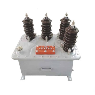
For Substation Metering & Protection: SJW-3 11kV Cast-Resin Voltage Transformer per IEC 61869-3
Introduction to the SJW-3 Voltage Transformer
The SJW-3 is a single-phase, cast-resin insulated voltage transformer (VT) engineered for precise voltage transformation in 11kV (IEC standard) or 10kV (domestic equivalent) medium-voltage power systems. Designed in strict compliance with IEC 61869-3 and GB/T 20840.3, it provides standardized secondary outputs—typically 100 V or 100/√3 V—for interfacing with revenue metering, protective relays, synchro-check devices, and power quality monitoring equipment. Its primary function is to isolate high-voltage circuits from low-voltage instrumentation while maintaining metrological integrity under normal and transient conditions.
Operating Principle of Cast-Resin Insulation
Cast-resin insulation in the SJW-3 employs vacuum pressure impregnation (VPI) technology using cycloaliphatic epoxy resin systems. This process eliminates air voids and moisture ingress by fully encapsulating the primary and secondary windings around a grain-oriented electrical steel (GOES) core. The resulting monolithic structure offers superior dielectric strength (≥30 kV/mm), excellent tracking resistance (CTI ≥600 V), and minimal partial discharge activity (<5 pC at 1.2 × Ur). Unlike oil-filled alternatives, the solid dielectric ensures no risk of leakage, fire hazard, or environmental contamination—critical for indoor substations, urban distribution centers, and confined industrial facilities. Thermal class F (155°C) insulation allows continuous operation at ambient temperatures up to 40°C with a 10K hotspot temperature rise margin.
Advantages Over Oil-Immersed Designs
Compared to traditional oil-immersed VTs, the SJW-3’s cast-resin construction delivers significant operational and safety benefits. It requires zero maintenance related to fluid levels or dielectric testing, eliminating annual oil sampling and associated disposal costs. The absence of flammable oil reduces fire load classification per IEC 61439, enabling installation in buildings with stringent fire codes. Additionally, the compact footprint (typically 30–40% smaller than oil equivalents) facilitates retrofitting into existing switchgear bays. Mechanical robustness against seismic loads (up to 0.5g horizontal acceleration per IEC 60068-2-57) and resistance to pollution (IP54 rating when mounted vertically) further enhance reliability in harsh environments. Long-term stability is assured by low thermal expansion mismatch between copper windings and epoxy matrix, preventing microcracking over 25+ years of service.
Typical Applications Overview
The SJW-3 is deployed across diverse infrastructure where accurate voltage sensing and system protection are paramount. In utility-owned 11kV ring main units (RMUs), it enables kWh metering for commercial billing and directional earth-fault detection. Industrial plants use it for motor protection coordination and harmonic distortion monitoring on 10kV busbars. Renewable integration points—such as solar farm collector substations—rely on its phase-angle stability for anti-islanding relays and SCADA telemetry. Rural electrification projects benefit from its maintenance-free operation in unattended pole-mounted cabinets. Crucially, its design accommodates both grounded and ungrounded neutral systems, supporting wye-connected configurations with or without auxiliary windings for residual voltage measurement.
Technical Specifications
The SJW-3 voltage transformer is defined by precise electrical and environmental parameters aligned with international standards. Below is a representative specification table for the standard model:
| Parameter | Value |
|---|---|
| Primary Voltage (Ur) | 11 kV (IEC) / 10 kV (GB) |
| Secondary Voltage | 100 V or 100/√3 V (per IEC 61869-3) |
| Voltage Ratio | 11000/100 V or 11000/100/√3 V |
| Accuracy Class | 0.2/3P or 0.5/3P (dual burden) |
| Rated Output (VA) | 30 VA (Class 0.2), 50 VA (Class 3P) |
| Insulation Level (LI/AC) | 75 kV / 28 kV (per IEC 60071-1) |
| Short-Time Withstand Current | Not applicable (VTs are not current-carrying under fault) |
| Frequency | 50 Hz ±0.5 Hz |
| Core Material | Grain-Oriented Electrical Steel (GOES), 0.27 mm lamination |
| Insulation System | Cycloaliphatic epoxy resin, VPI process, Class F (155°C) |
| Partial Discharge | <5 pC at 1.2 × Ur |
Standard Service Conditions
The SJW-3 is rated for operation under IEC 60060-1 standard atmospheric conditions: ambient temperature range of –25°C to +40°C, relative humidity ≤95% (non-condensing), and altitude ≤1000 m above sea level. For installations above 1000 m, dielectric strength must be derated by 1% per 100 m increment per IEC 60071-2. The transformer withstands daily thermal cycling without performance degradation due to matched coefficients of thermal expansion between copper (17×10⁻⁶/°C) and epoxy resin (50–60×10⁻⁶/°C). Condensation resistance is enhanced by hydrophobic surface treatment and absence of internal cavities. In coastal or chemical-industrial zones (pollution degree 3 per IEC 60664-1), creepage distance exceeds 25 mm/kV (phase-to-ground), ensuring reliable operation under salt fog or sulfur dioxide exposure.
Accuracy and Burden Characteristics
Dual-accuracy-class design allows simultaneous connection of metering (Class 0.2) and protection (Class 3P) burdens. At rated load (30 VA for metering, 50 VA for protection), voltage error remains within ±0.2% and phase displacement ≤10 minutes for Class 0.2. Under protection burden at 3× rated voltage (33 kV), Class 3P maintains error ≤±3.0% and phase error ≤120 minutes—sufficient for overvoltage and undervoltage relay operation. Burden impedance must be purely resistive or inductive; capacitive loads exceeding 0.1 µF can induce ferroresonance. To mitigate this, the SJW-3 incorporates inherent damping via optimized core saturation characteristics and optional secondary damping resistors (typically 100–500 Ω, 50 W).
Typical Applications
The SJW-3 voltage transformer serves critical roles across modern power infrastructure, leveraging its cast-resin reliability and IEC-certified accuracy.
Substation Secondary Metering
In 11kV primary substations feeding urban distribution networks, the SJW-3 provides the reference voltage for revenue-grade kWh meters compliant with IEC 62053-22 Class 0.2S. Its low phase displacement ensures accurate reactive energy measurement (kVArh), essential for power factor billing. When installed in metal-enclosed switchgear (e.g., ABB SafeRing or Siemens 8DJH), it interfaces directly with digital multifunction meters via shielded twisted-pair cables (min. 2.5 mm² cross-section). The 100/√3 V secondary output supports wye-connected metering in effectively grounded systems, while the 100 V version suits corner-grounded delta configurations. Calibration traceability to national standards (e.g., NIST or PTB) is maintained through factory test certificates per IEC 61869-3 Annex B.
Industrial Power Distribution
Large manufacturing facilities operating on 10kV internal distribution rely on the SJW-3 for motor protection and power quality monitoring. Connected to feeder breakers, it supplies voltage inputs to multifunction relays (e.g., SEL-751 or GE Multilin 369) for loss-of-potential (LOP) blocking, reverse power detection, and voltage unbalance tripping. In arc furnace or welding plant environments with high harmonic distortion (THDv >5%), the GOES core’s low hysteresis loss minimizes heating under non-sinusoidal excitation. Secondary circuits are routed through grounded metallic conduits to suppress electromagnetic interference from variable-frequency drives (VFDs). The VT’s short-time thermal withstand (1 s at 2× Ur) protects against transient overvoltages during capacitor bank switching.
Renewable Energy Integration
Solar photovoltaic (PV) and wind farms integrate the SJW-3 at the 11kV collector substation to support grid compliance functions. It provides voltage signals to anti-islanding relays that detect loss of mains by monitoring rate-of-change-of-frequency (ROCOF) and vector shift. For grid code adherence (e.g., ENTSO-E or IEEE 1547), the VT must maintain accuracy during low-voltage ride-through (LVRT) events down to 0.15× Ur for 150 ms—achieved via linear core operation in the knee-point region. Inverter-based resources also use its output for reactive power control (Q(V) droop), requiring phase stability within ±0.5° over –10°C to +50°C ambient swings. The cast-resin housing resists UV degradation in outdoor combiner boxes, eliminating the need for climate-controlled enclosures.
Rural and Suburban Distribution Networks
In remote or semi-urban areas with limited maintenance access, the SJW-3’s hermetic sealing ensures decades of trouble-free operation. Mounted on poles or in pad-mounted transformers, it enables remote voltage monitoring via cellular RTUs for distribution automation (DA) schemes like FLISR (Fault Location, Isolation, and Service Restoration). The 10kV domestic variant aligns with China’s GB standard grid nominal voltage, facilitating deployment in township electrification projects. Its lightweight design (typically 25–35 kg) simplifies manual handling during installation, while M12 stainless steel terminals accept ring-lug or spade connectors up to 50 mm². Partial discharge immunity prevents premature aging in networks with frequent lightning-induced transients.
Compliance with International Standards
The SJW-3 voltage transformer is engineered to satisfy both global and regional regulatory frameworks, ensuring interoperability and safety across markets.
IEC 61869-3 Compliance Details
IEC 61869-3:2011 (“Instrument transformers – Part 3: Additional requirements for inductive voltage transformers”) defines the core performance criteria for the SJW-3. Key compliance aspects include: (1) Accuracy verification under sinusoidal conditions at 80–120% of rated voltage and 25–100% of rated burden; (2) Temperature rise limits (≤55 K for windings, measured by resistance method); (3) Dielectric tests comprising 1-minute power frequency withstand (28 kV rms) and lightning impulse (75 kV peak, 1.2/50 µs wave); (4) Short-circuit withstand capability simulated via open-circuit secondary during primary overvoltage. The standard mandates type tests (conducted once per design), routine tests (100% production), and sample tests (per batch). Factory reports include ratio error, phase displacement, and partial discharge measurements traceable to ISO/IEC 17025-accredited labs.
Alignment with GB/T 20840.3
GB/T 20840.3-2013 mirrors IEC 61869-3 but includes China-specific adaptations. Notably, it permits 10kV as the nominal system voltage (vs. IEC’s 11kV), adjusts insulation levels for 50 Hz systems (LI/AC = 75/30 kV for 10kV class), and specifies tighter accuracy tolerances for Class 0.2 (±0.15% voltage error). The SJW-3 meets both by designating dual nameplate ratings: “11/√3 kV / 100/√3 V” for IEC and “10/√3 kV / 100/√3 V” for GB applications. Chinese grid codes (e.g., State Grid Q/GDW 13001) additionally require seismic qualification per GB 50260, which the SJW-3 satisfies through finite element analysis (FEA)-validated mounting brackets rated for 8-degree intensity zones.
Testing and Certification Requirements
Certification involves third-party validation by bodies such as KEMA (now DNV), CESI, or CEPREI. Type tests include temperature rise (per IEC 60060-2), short-time dynamic behavior under ferroresonance (IEC TR 61869-103), and mechanical endurance (vibration at 10–55 Hz, 0.35 mm amplitude). Routine production tests cover: (1) Polarity check (reducing polarity confirmed via DC kick test); (2) Turns ratio verification (±0.1% tolerance); (3) Insulation resistance (>1000 MΩ at 2500 V DC); (4) Power frequency withstand (28 kV for 1 min, leakage current <1 mA). Each unit ships with a test certificate listing serial number, test date, and measured parameters.
On-Site Testing Procedures
Post-installation verification ensures the SJW-3 performs within specifications before energization. All tests follow IEC 60060-1 and IEEE C57.13.6 protocols.
Insulation Resistance Test
Using a 2500 V DC megohmmeter, measure insulation resistance between primary winding and ground, secondary winding and ground, and inter-winding. Acceptance criterion: ≥1000 MΩ at 20°C. Correct for temperature using R₂₀ = Rₜ × 2^((20−t)/10). Low readings indicate moisture ingress or resin cracking—requiring drying or replacement. Perform before and after dielectric tests to detect insulation damage.
Turns Ratio Test
Apply 100–200 V AC (50 Hz) to the primary and measure secondary voltage with a calibrated true-RMS voltmeter. Calculate ratio as Vₚ/Vₛ. Tolerance: ±0.1% of nameplate value. For 11000/100 V VT, measured ratio must be 110.0 ±0.11. Deviations suggest turn-to-turn shorts or incorrect tap selection. Use a dedicated ratio tester (e.g., Omicron CT Analyzer) for automated comparison.
Polarity Test
Confirm reducing polarity (IEC standard) via DC method: connect battery (+) to primary H1, (–) to H2; connect galvanometer (+) to secondary X1, (–) to X2. Momentary closure should produce positive deflection. Incorrect polarity causes 180° phase reversal, leading to metering errors or relay misoperation. Verify with oscilloscope if AC method is preferred (apply low-voltage sine wave and compare zero-crossing alignment).
Power Frequency Withstand Voltage Test
Apply 28 kV rms (50 Hz) between primary and ground/secondary for 1 minute. Secondary windings are short-circuited and grounded. Monitor leakage current—it must remain <1 mA and show no sudden jumps. Failure indicates insulation breakdown. Reduce test voltage to 80% (22.4 kV) for maintenance retesting per IEC 60270. Always discharge windings post-test using grounding sticks.
Open-Circuit Characteristic Test
With secondary open, gradually increase primary voltage from 0 to 190 V (≈1.2× secondary rated voltage reflected to primary). Plot exciting current vs. voltage. Knee-point voltage (where current rises sharply) should exceed 1.5× rated secondary voltage (150 V). Low knee-point indicates core saturation risk during ferroresonance. Exciting current at 100 V should be <0.5% of rated primary current (≈0.5 mA for 11kV/100V VT).
Preventive Maintenance Guide
Although cast-resin VTs require minimal upkeep, periodic checks extend service life and prevent unexpected failures.
Periodic Inspection Protocol
Conduct visual and thermographic inspections annually. Check for: (1) Surface cracks or tracking marks on resin housing; (2) Corrosion on terminals or mounting hardware; (3) Loose connections (torque to 15 N·m for M12 studs); (4) Abnormal heating via IR camera (ΔT >10 K above ambient warrants investigation). Clean housing with dry cloth—never use solvents that degrade epoxy. Verify secondary circuit integrity: insulation resistance >100 MΩ and burden impedance within specified range. Record findings in asset management software for trend analysis.
Maintenance Intervals and Fault Diagnosis
Replace only if critical faults occur—no scheduled component replacement is needed. Common failure modes include: (1) Secondary winding open-circuit (detected by infinite insulation resistance or zero secondary voltage); (2) Core saturation due to ferroresonance (evidenced by overheating and distorted secondary waveform); (3) Terminal arcing from loose connections (visible as pitting or carbon tracking). Every 5 years, repeat insulation resistance and ratio tests. After system faults (e.g., lightning strikes), perform partial discharge scan using HFCT sensors—readings >20 pC indicate internal degradation. Expected service life is 25–30 years under standard conditions; derate by 5 years per 10°C average ambient above 30°C.
| Interval | Action | Acceptance Criteria |
|---|---|---|
| Annual | Visual + Thermographic Inspection | No cracks, ΔT ≤10 K |
| 5 Years | Insulation Resistance + Ratio Test | ≥1000 MΩ, ±0.1% ratio |
| Post-Fault | Partial Discharge Scan | <10 pC at 1.2× Ur |
Conclusion
The SJW-3 11kV cast-resin voltage transformer represents a benchmark in medium-voltage instrumentation, combining IEC 61869-3-certified metrological performance with the ruggedness demanded by modern power systems. Its vacuum-pressure-impregnated epoxy encapsulation eliminates the fire, leakage, and maintenance liabilities inherent in oil-filled designs, while the GOES core ensures exceptional linearity across metering and protection burdens. Engineered for both 11kV (IEC) and 10kV (GB) networks, it seamlessly integrates into utility substations, industrial plants, renewable generation sites, and rural distribution infrastructure. Rigorous compliance with international standards guarantees interoperability, and its 25–30 year design life minimizes total cost of ownership. With precise on-site testability and minimal preventive maintenance requirements, the SJW-3 delivers sustained accuracy, safety, and reliability—making it an optimal choice for engineers prioritizing long-term system integrity over initial procurement cost.
Frequently Asked Questions (FAQ)
Q1: Can the SJW-3 be used in ungrounded 11kV systems?
Yes. The SJW-3 supports both grounded and ungrounded (isolated neutral) 11kV systems. In ungrounded configurations, it is typically connected phase-to-ground with the secondary neutral left floating or grounded at one point per IEC 61869-3 Clause 7.4. However, ferroresonance risk increases in ungrounded systems during single-line-to-ground faults. Mitigation measures include: (1) Using Class 3P accuracy with inherent core damping; (2) Installing secondary damping resistors (100–500 Ω, 50 W) across one secondary winding; (3) Avoiding capacitive burdens. The transformer’s design includes sufficient magnetic shunt to suppress resonant overvoltages up to 2.5× Ur.
Q2: What is the maximum allowable secondary burden for Class 0.2 accuracy?
For Class 0.2 accuracy, the total secondary burden—including lead resistance—must not exceed 30 VA at unity power factor. Assuming 100 V secondary, this corresponds to a minimum load impedance of Z = V²/S = 100²/30 ≈ 333 Ω. Lead resistance should be ≤0.5 Ω (using 2.5 mm² Cu cable over ≤50 m round-trip). Exceeding 30 VA shifts the operating point into nonlinear core regions, increasing ratio error beyond ±0.2%. Always verify burden during commissioning using a precision wattmeter or impedance bridge.
Q3: How does altitude affect the SJW-3’s dielectric performance?
Above 1000 m altitude, air density decreases, reducing dielectric strength. Per IEC 60071-2, the power frequency withstand voltage must be derated by 1% per 100 m above 1000 m. For example, at 2000 m, the 28 kV test voltage becomes 28 × [1 – 0.01×(2000–1000)/100] = 25.2 kV. Similarly, lightning impulse withstand drops from 75 kV to 67.5 kV. The SJW-3’s solid epoxy insulation is unaffected by altitude, but external clearances (phase-to-phase and phase-to-ground) must be increased per IEC 61439-2. Inform the manufacturer for altitudes >2000 m to adjust creepage distances.
Q4: Is the SJW-3 suitable for harmonic-rich environments?
Yes, with caveats. The GOES core exhibits low additional losses under harmonic excitation compared to non-oriented steel. However, voltage harmonics (especially 3rd, 5th, 7th) can cause core saturation if their RMS sum exceeds 5% of fundamental (per IEC 61000-4-30). In such cases, select a VT with higher thermal rating or derate the burden by 20%. Never connect capacitive filters directly to the secondary—this creates series resonance at harmonic frequencies. For THDv >8%, consider adding a small air-core reactor (0.5–1 mH) in series with the secondary to block harmonic currents.
Q5: What distinguishes IEC 11kV from domestic 10kV ratings?
IEC 60038 defines 11kV as the standard nominal voltage for 10–11 kV class systems, accounting for ±10% operational tolerance (9.9–12.1 kV). China’s GB standard uses 10kV nominal (9–11 kV range). The SJW-3 accommodates both via dual nameplate labeling. Electrically, the insulation level (75/28 kV) is identical, but accuracy tests for GB applications use 10kV primary voltage. When replacing legacy 10kV oil VTs, the SJW-3’s 11kV rating provides a 10% voltage margin, enhancing longevity during system overvoltages.
Q6: Can multiple relays be connected to one SJW-3 secondary?
Yes, provided the total burden does not exceed the rated VA for the required accuracy class. For example, connecting two 15 VA relays (total 30 VA) is acceptable for Class 0.2 metering. However, ensure all devices share a common ground point to avoid circulating currents. Use separate cores if available (some VTs offer dual secondaries). Never daisy-chain grounds—this creates ground loops inducing measurement errors. For protection-class connections (Class 3P, 50 VA), up to