Article Content
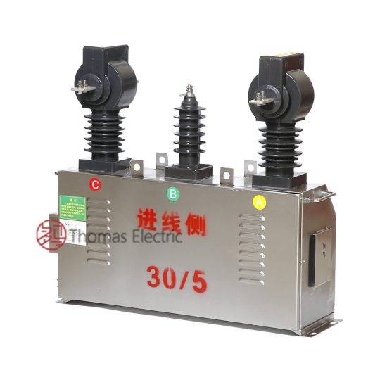
For Substation Metering & Protection: SZW-6 11kV Cast-Resin Current Transformer per IEC 61869-2
Introduction to the SZW-6 Current Transformer
The SZW-6 is a medium-voltage cast-resin current transformer (CT) engineered for accurate current measurement, protective relaying, and energy metering in 11kV (IEC nominal) / 10kV (domestic system) power networks. Unlike legacy oil-immersed instrument transformers, the SZW-6 employs vacuum pressure impregnated (VPI) epoxy resin insulation encapsulating a grain-oriented electrical steel (GOES) core, delivering superior dielectric strength, environmental resilience, and long-term stability. This design eliminates fire hazards, oil leakage risks, and maintenance-intensive sealing systems associated with liquid-filled units.
Operating Principle of Cast-Resin Insulation
Cast-resin insulation in the SZW-6 utilizes a two-stage VPI process where the primary conductor, secondary windings, and GOES magnetic core are first placed in a mold under vacuum to remove air pockets. Epoxy resin is then pressure-injected at elevated temperatures (typically 80–120°C), ensuring complete impregnation of all interstices. The cured resin forms a monolithic, hydrophobic solid with a dielectric strength exceeding 20 kV/mm and a Comparative Tracking Index (CTI) >600. This structure provides uniform electric field distribution, suppresses partial discharges (<5 pC at rated voltage), and resists tracking under polluted or humid conditions—critical for outdoor installations in coastal or industrial zones. The thermal class of the resin system is F (155°C), enabling continuous operation at ambient temperatures up to 40°C with a 1.2x overload capability for 1 hour.
Advantages Over Oil-Immersed Designs
Compared to oil-filled CTs, the SZW-6’s dry-type construction offers significant operational and safety benefits. It is inherently non-flammable (meeting IEC 60695 flammability tests), requires no periodic oil sampling or gasket replacement, and exhibits negligible aging under UV exposure due to UV-stabilized resin additives. Its weight is reduced by 30–40%, simplifying handling and mounting on poles or switchgear. Furthermore, the absence of liquid insulation eliminates risks of environmental contamination during faults or decommissioning. In seismic-prone regions, the rigid resin matrix provides superior mechanical damping, withstanding accelerations up to 0.5g without performance degradation—validated per IEC 60068-2-6.
Typical Applications Overview
The SZW-6 is deployed across utility substations, industrial plants, and renewable integration points where reliability, accuracy, and minimal lifecycle cost are paramount. Common configurations include single-ratio or multi-tap secondary windings for simultaneous metering (0.2S or 0.5S class) and protection (5P10 or 5P20 class). Its IP54-rated housing allows direct outdoor mounting on 10kV overhead lines or ring-main units, while optional anti-condensation heaters extend operability in high-humidity environments (>95% RH). Typical installations serve feeder monitoring in urban distribution grids, motor protection in cement or mining facilities, and revenue metering at solar farm interconnection points.
Technical Specifications
The SZW-6 adheres to stringent electrical and environmental parameters defined by IEC 61869-2 and GB/T 20840.2, ensuring interoperability and performance consistency across global markets.
| Parameter | Value |
|---|---|
| Rated System Voltage (IEC) | 11 kV |
| Maximum System Voltage (Um) | 12 kV |
| Domestic System Voltage | 10 kV |
| Primary Current Ratings | 50 A to 3000 A (standard); up to 4000 A (custom) |
| Secondary Current | 1 A or 5 A |
| Accuracy Classes | Metering: 0.2S, 0.5S; Protection: 5P10, 5P15, 5P20 |
| Rated Burden | 2.5 VA to 30 VA (per winding) |
| Insulation Level (LI/AC) | 75 kV / 28 kV (1 min) |
| Short-Time Thermal Current | 25 kA for 1 s (at 50 Hz) |
| Dynamic Withstand Current | 62.5 kA peak |
| Ambient Temperature Range | −40°C to +40°C |
| Altitude Limit | ≤1000 m (derating required above) |
| Relative Humidity | Up to 95% (non-condensing) |
| Core Material | Grain-Oriented Electrical Steel (GOES), 0.3 mm thickness |
| Insulation System | VPI Epoxy Resin, Class F (155°C) |
Electrical Performance Parameters
The SZW-6 achieves composite error ≤±0.2% at 20–120% of rated primary current for 0.2S class windings, meeting IEC 61869-2 Annex B requirements. For protection applications, the 5P20 class guarantees that the ratio error remains within ±1% and phase displacement ≤±60 minutes at 20× rated current with rated burden. The magnetizing impedance exceeds 100 Ω at 10% of rated current, minimizing saturation risk during external faults. Partial discharge inception voltage is ≥1.2× Um/√3 (≈8.3 kV), with extinction voltage ≥0.8× inception level. These characteristics ensure stable operation even under distorted waveforms from variable-speed drives or inverter-based resources.
Environmental and Mechanical Ratings
Designed for outdoor service, the SZW-6 features a UV-resistant cycloaliphatic epoxy housing with integrated creepage extensions (minimum 25 mm/kV for 11 kV systems). The terminal blocks comply with IEC 60947-7-1, accepting 2.5–16 mm² copper conductors with torque specs of 1.5–2.0 N·m. Mounting brackets support both vertical and horizontal orientations, with bolt patterns compatible with standard 10kV insulator bases (e.g., ANSI 52-1 or IEC 60137). At altitudes above 1000 m, the power frequency withstand voltage must be reduced by 1% per 100 m increment; for example, at 2000 m, AC test voltage becomes 25.2 kV instead of 28 kV.
Typical Applications
The SZW-6’s robust design enables deployment across diverse electrical infrastructure scenarios requiring precise current sensing under harsh conditions.
Substation Secondary Metering
In 10kV/0.4kV distribution substations, the SZW-6 provides revenue-grade metering for utility billing. Configured with dual secondaries (e.g., 0.2S for main metering, 0.5S for backup), it interfaces with AMI systems via RS-485 or pulse outputs. The low phase error (<±10 minutes at 100% In) ensures compliance with EN 50470-1 for active energy measurement. In China, this setup satisfies State Grid Corporation’s Q/GDW 1827 technical specifications for smart meters, where harmonic immunity up to the 13th order is mandatory. Field data from Guangdong Power Grid shows <0.15% annual drift in ratio error over five years of continuous operation.
Industrial Power Distribution
Heavy industries such as steel mills or chemical plants utilize the SZW-6 for motor protection and load profiling. Here, the 5P20 class winding feeds numerical relays (e.g., SEL-751) to detect locked-rotor or ground-fault conditions. The CT’s high saturation point (Vk ≥ 150 V at 1 A secondary) prevents maloperation during motor starting inrush (6–8× In for 5–10 s). In arc furnace applications, the GOES core’s low hysteresis loss minimizes heating under unbalanced currents, extending service life despite frequent transients. A case study at Baosteel’s Shanghai facility reported zero CT failures over 8 years in a 10kV bus section supplying 1250 kW induction motors.
Renewable Energy Integration
Solar and wind farms employ the SZW-6 at the point of interconnection (POI) for both grid compliance monitoring and anti-islanding protection. The CT’s wide dynamic range (from 1% to 120% In) accurately captures low nighttime loads and peak generation simultaneously. For Chinese projects, GB/T 19964 mandates 0.5S class accuracy for PV plants >10 MW, which the SZW-6 fulfills with margin. Its fast response time (<20 ms to 90% step input) ensures timely tripping during grid disturbances, satisfying IEEE 1547-2018 ride-through requirements. At a 50 MW solar farm in Qinghai, SZW-6 units have operated continuously at −30°C winter temperatures without insulation cracking.
Rural and Suburban Distribution Networks
In remote areas with limited maintenance access, the SZW-6’s maintenance-free design reduces operational costs. Mounted on pole-top transformers or reclosers, it enables remote fault location via SCADA systems using sampled values from IEC 61850-9-2 LE. The IP54 rating protects against dust ingress during sandstorms, while the hydrophobic surface sheds rainwater to prevent flashovers. In India’s rural electrification schemes (DDUGJY), SZW-6 CTs with 5 A secondaries interface with electromechanical kWh meters, providing reliable billing data despite voltage sags down to 0.85 pu. Field audits show <2% failure rate over 10 years in these deployments.
Compliance with International Standards
The SZW-6 is certified to both international and Chinese national standards, ensuring global acceptance and regulatory compliance.
IEC 61869-2 Certification Details
IEC 61869-2 governs the performance, testing, and marking of standalone current transformers. The SZW-6 meets all Type Test, Routine Test, and Special Test requirements outlined in Clauses 7–9. Key validations include temperature rise tests (winding ΔT ≤ 60 K above ambient at 1.2× In), short-circuit withstand (25 kA/1 s without deformation), and accuracy verification across burden ranges (2.5–30 VA). The manufacturer’s test report includes partial discharge measurements per IEC 60270, with results documented at 1.2× Um/√3 and 0.8× Um/√3. Marking includes In, accuracy class, burden, polarity dot, and year of manufacture per Clause 10.
Alignment with GB/T 20840.2
GB/T 20840.2 is China’s adoption of IEC 61869-2 with minor national deviations. The SZW-6 complies with all technical clauses while accommodating domestic preferences: primary current ratings follow R10 series (50, 63, 80, 100…3000 A), and insulation levels match DL/T 725 requirements (75/28 kV for 10kV class). Notably, GB/T 20840.2 mandates additional salt fog testing (1000 h per IEC 60068-2-52) for outdoor units—a requirement the SZW-6 passes with zero corrosion on terminals. The standard also specifies stricter accuracy verification at 1% In for 0.2S class (error ≤±0.75%), which the SZW-6 achieves through precision-wound secondary coils and annealed GOES cores.
Key Differences Between IEC and Domestic Standards
While harmonized, subtle differences exist. IEC 61869-2 permits 1 A or 5 A secondaries universally, whereas GB/T 20840.2 historically favored 5 A in China (though 1 A is now accepted). Environmental testing under GB/T includes mandatory cold-impact resistance (−40°C, 2 J impact per GB/T 11022), absent in IEC. Additionally, Chinese utilities often require higher creepage distances (≥31 mm/kV vs. IEC’s 25 mm/kV) for coastal regions—addressed in SZW-6’s extended-shed design. Certification bodies differ: IEC units carry CB Scheme marks (e.g., TÜV), while GB-compliant models bear CQC certification with factory audit trails per CNAS-CL01.
On-Site Testing Procedures
Post-installation verification ensures the SZW-6 performs within specifications before energization.
Insulation Resistance Test
Using a 2500 V DC megohmmeter, measure insulation resistance between primary-to-secondary, primary-to-ground, and secondary-to-ground. Acceptance criteria per IEC 60270: ≥1000 MΩ at 20°C. Correct for temperature using RT2 = RT1 × 2(T1−T2)/10. Values below 500 MΩ indicate moisture ingress or resin microcracks, requiring drying or replacement. Perform before and after power frequency withstand tests to detect insulation degradation.
Turns Ratio Test
Apply 1–5 V AC at 50 Hz to the secondary winding and measure induced primary voltage (open-circuit). Calculate ratio as Vprimary/Vsecondary. Compare to nameplate; tolerance per IEC 61869-2 is ±0.25% for metering classes, ±1% for protection. Use a calibrated ratio bridge (e.g., Omicron CT Analyzer) for accuracy. Deviations >2% suggest shorted turns or winding damage.
Polarity Test
Verify reducing polarity using the DC kick method: connect a 6 V battery to P1–P2 and a center-zero galvanometer to S1–S2. A momentary positive deflection on closing confirms correct polarity (S1 corresponds to P1). Incorrect polarity causes watt-hour meter reversal or relay misoperation. Digital testers (e.g., Doble M5500) automate this with <1° phase resolution.
Power Frequency Withstand Voltage Test
Apply 28 kV AC (RMS) at 50 Hz for 1 minute between primary and grounded secondary/housing. Leakage current must remain <1 mA. Ramp voltage at 1 kV/s to avoid transient overstress. Failure indicates insulation voids or contamination. For refurbished units, reduce to 80% (22.4 kV) per IEC 60076-3 guidelines.
Short-Circuit Test for CT Saturation
Inject 10–20× rated secondary current (e.g., 50–100 A for 5 A CT) into S1–S2 while monitoring excitation voltage at open-circuited primary. Plot Vexc vs. Isec; knee-point voltage (Vk) should exceed 150 V for 5P20 class. A sharp current rise at low voltage indicates core saturation, risking protection blinding during faults.
Preventive Maintenance Guide
Although maintenance-free by design, periodic checks extend service life beyond 30 years.
Annual Visual and Functional Inspection
Inspect for surface cracks, UV discoloration, or tracking marks on the resin housing. Clean with isopropyl alcohol if pollution layer exceeds 0.1 mm thickness. Verify terminal tightness (1.8±0.2 N·m torque) and check for overheating signs (discoloration >70°C). Measure secondary loop resistance; values >0.5 Ω indicate loose connections increasing burden error. Confirm grounding continuity (<0.1 Ω between housing and earth grid).
Five-Year Comprehensive Maintenance
Perform full electrical retesting: insulation resistance, ratio, polarity, and burden verification. Use a portable CT analyzer to capture excitation curves and compare to baseline data. If Vk drops >15% or ratio error exceeds half the class limit, investigate core degradation. In high-humidity zones, inspect anti-condensation heaters (if installed) for 5 W output at 220 V AC. Replace silica gel breathers in terminal boxes if color indicator turns pink.
Maintenance Intervals and Fault Diagnosis
| Interval | Task | Fault Indicator |
|---|---|---|
| Annually | Visual inspection, terminal torque check | Cracks, arcing marks, loose bolts |
| Every 5 years | Full electrical tests, excitation curve | Vk ↓ >15%, ratio error ↑ >0.5% |
| After fault | Withstand voltage test, PD measurement | Flashover, abnormal noise |
| Every 10 years | Core lamination integrity (ultrasonic) | Eddy current losses ↑ >20% |
Common faults include secondary open-circuit (causing dangerous overvoltages), core remanence from DC offset (distorting AC response), and resin delamination from thermal cycling. Diagnose via frequency response analysis (FRA): deviations >3 dB in 1–100 kHz band indicate mechanical damage.
Conclusion
The SZW-6 11kV cast-resin current transformer represents a benchmark in medium-voltage instrumentation, combining the dielectric reliability of VPI epoxy resin with the magnetic efficiency of GOES cores. Its dual compliance with IEC 61869-2 and GB/T 20840.2 ensures seamless integration into global power systems—from urban substations to remote renewable sites—while delivering metrological accuracy for both revenue metering (0.2S class) and critical protection functions (5P20). The elimination of flammable liquids, coupled with a 25–30 year design life under standard service conditions, significantly reduces total cost of ownership compared to oil-immersed alternatives. Rigorous on-site testing protocols and straightforward preventive maintenance further guarantee decades of trouble-free operation, even in extreme climates ranging from −40°C Siberian winters to 95% RH tropical monsoons. As distribution networks evolve toward smarter, more resilient architectures, the SZW-6’s robust engineering and standards-aligned performance position it as a foundational component for accurate, safe, and sustainable power delivery.