Article Content
IEC 61869-3 Certified 11kV Cast-Resin Voltage Transformer VT-10K for Metering & Protection Applications
Introduction to the VT-10K Voltage Transformer
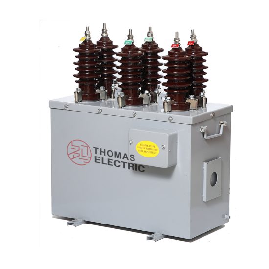
The VT-10K is a single-phase, indoor/outdoor-rated cast-resin voltage transformer (VT) engineered for reliable operation in 11 kV (IEC nominal) or 10 kV (domestic system) medium-voltage networks. Designed in strict accordance with IEC 61869-3 and GB/T 20840.3, this instrument transformer provides galvanic isolation between high-voltage primary circuits and low-voltage secondary instrumentation, enabling safe and accurate voltage measurement for metering, revenue billing, and protective relaying functions. Its robust construction eliminates fire hazards and environmental risks associated with oil-filled alternatives, making it ideal for urban substations, industrial facilities, and renewable energy interconnection points.
Operating Principle of Cast-Resin Insulation
Cast-resin insulation in the VT-10K employs vacuum pressure impregnation (VPI) of cycloaliphatic epoxy resin around precision-wound copper windings and grain-oriented electrical steel (GOES) cores. This process ensures complete void-free encapsulation, preventing partial discharge inception even under transient overvoltages. The resin matrix exhibits high dielectric strength (>20 kV/mm), excellent tracking resistance (CTI >600 V), and thermal stability up to 130°C. Unlike oil-immersed VTs, the solid dielectric eliminates leakage paths, moisture ingress, and flammability concerns—critical for installations near public infrastructure or in confined spaces. The homogeneous thermal expansion coefficient between resin and metallic components minimizes mechanical stress during thermal cycling, enhancing long-term reliability over a 25–30 year service life.
Advantages Over Oil-Immersed Designs
The VT-10K’s dry-type cast-resin construction offers significant operational and safety advantages compared to traditional oil-filled voltage transformers. First, it requires zero maintenance related to fluid levels, gas analysis, or sealing integrity. Second, its non-flammable nature complies with stringent fire codes (e.g., IEC 61537) for indoor switchgear rooms and underground substations. Third, the compact footprint—enabled by higher insulation efficiency—reduces spatial requirements by up to 40%. Additionally, cast-resin VTs exhibit superior short-circuit withstand capability due to rigid winding fixation, eliminating conductor displacement during fault currents. Environmental compliance is also enhanced: no PCBs, mineral oils, or SF6 are used, aligning with RoHS and WEEE directives. These attributes make the VT-10K particularly suitable for smart grid deployments where reliability, safety, and minimal lifecycle costs are paramount.
Typical Application Overview
The VT-10K serves as a foundational component in secondary systems requiring precise voltage representation. In utility substations, it feeds analog inputs to revenue meters (Class 0.2 or 0.5 per IEC 61869-3) and digital protective relays (e.g., distance, overvoltage, or undervoltage elements). Industrial plants utilize it for power quality monitoring and motor protection schemes. Renewable integration projects—such as solar farms or wind parks—deploy the VT-10K at the point of common coupling (PCC) to satisfy grid code requirements for voltage regulation and anti-islanding detection. Its dual secondary windings (e.g., 100/√3 V and 100/3 V) support simultaneous metering and protection functions without cross-interference. The transformer’s low burden requirement (<30 VA) ensures compatibility with modern microprocessor-based devices while maintaining accuracy under light-load conditions.
Technical Specifications
The VT-10K is engineered to deliver consistent performance under defined electrical and environmental parameters. All specifications comply with IEC 61869-3:2011 (Instrument transformers – Part 3: Additional requirements for inductive voltage transformers) and its Chinese counterpart GB/T 20840.3-2013.
| Parameter | Value |
|---|---|
| System Voltage (Um) | 12 kV (IEC), 11.5 kV (GB) |
| Primary Voltage (Rated) | 11/√3 kV (IEC), 10/√3 kV (Domestic) |
| Secondary Voltage(s) | 100/√3 V, 100/3 V (standard); custom ratios available |
| Accuracy Class | Metering: 0.2, 0.5; Protection: 3P, 6P |
| Rated Output (per winding) | 10–100 VA (configurable) |
| Burden Power Factor | 0.8 lagging (standard) |
| Insulation Level (LI/AC) | 75/42 kV (per IEC 60071-1) |
| Short-Circuit Withstand | 1 s, 16 kA RMS (primary side) |
| Temperature Rise Limit | ≤60 K (at rated output, ambient 40°C) |
| Ambient Temperature Range | –25°C to +40°C (indoor/outdoor) |
| Altitude Limit | ≤1000 m above sea level (derating required above) |
| Relative Humidity | ≤95% (non-condensing) |
| Core Material | Grain-Oriented Electrical Steel (GOES), 0.23 mm thickness |
| Insulation System | VPI cycloaliphatic epoxy resin, UL 94 V-0 rated |
Electrical Performance Parameters
The VT-10K achieves its specified accuracy classes through meticulous core lamination stacking and winding tension control. For metering class 0.2, voltage error must not exceed ±0.2% and phase displacement ≤±10 minutes at 80–120% of rated voltage and 25–100% of rated burden. Protection class 3P limits voltage error to ±3% and phase error to ±120 minutes under similar conditions but extended to 5%–190% of rated voltage to accommodate fault scenarios. The transformer’s magnetizing current is kept below 0.5 mA at rated voltage to minimize no-load losses (<15 W typical). Frequency response remains flat within ±0.1% from 48 Hz to 52 Hz, ensuring compatibility with variable-frequency generation sources. Dielectric tests include 1-minute AC withstand at 42 kV RMS (phase-to-ground) and lightning impulse at 75 kV peak (1.2/50 μs waveform), both passed without flashover or disruptive discharge.
Environmental and Mechanical Ratings
Designed for global deployment, the VT-10K operates reliably across diverse climatic zones. The cast-resin housing resists UV degradation (tested per IEC 60529 IP54 for outdoor use) and withstands salt fog exposure (IEC 60068-2-11) for coastal installations. Thermal performance is validated via temperature-rise tests per IEC 61869-3: at 100% load and 40°C ambient, the average winding temperature rise does not exceed 60 K, with hot-spot margin maintained below 75 K. Mechanical robustness is ensured through vibration testing (IEC 60068-2-6) simulating transport and seismic events (up to 0.3g horizontal acceleration). Terminal blocks are rated for 63 A continuous current with screw-type clamping (M8 bolts), compatible with standard 2.5–16 mm² copper conductors. Weight ranges from 28 kg (single secondary) to 35 kg (dual secondary), facilitating manual handling during installation.
Typical Applications
The VT-10K’s versatility stems from its dual-role capability in metering and protection circuits, supported by standardized secondary outputs and rigorous accuracy compliance.
Substation Secondary Metering Systems
In 11 kV distribution substations, the VT-10K supplies voltage signals to three-phase kWh meters for utility billing. Its Class 0.2 accuracy ensures compliance with regulatory standards (e.g., EN 50470-3) for revenue-grade metering. The 100/√3 V secondary output interfaces directly with static meters, eliminating the need for auxiliary transformers. Simultaneously, a second winding (100/3 V) feeds protective relays for earth-fault detection in resonant-grounded networks. The transformer’s low phase displacement (<5 minutes at 0.2 class) prevents vector group errors in directional overcurrent schemes. Installation typically occurs on busbar supports or circuit breaker poles, with secondary cabling routed through shielded conduits to mitigate electromagnetic interference from adjacent switchgear operations.
Industrial Power Distribution Networks
Large manufacturing facilities deploy the VT-10K at main incomers and critical feeder panels to monitor power quality and enable automated load shedding. For example, in automotive plants with sensitive robotic assembly lines, voltage sags below 90% of nominal trigger UPS engagement—requiring VTs with rapid response and minimal harmonic distortion. The VT-10K’s GOES core maintains linearity even under 5th and 7th harmonic injection (common with VFD loads), limiting ratio error increase to <0.1% at 5% THD. Its compact size allows retrofit into legacy switchboards without structural modifications. Additionally, the absence of oil simplifies compliance with OSHA and NFPA 70E safety protocols during maintenance windows.
Renewable Energy Integration Points
Solar photovoltaic (PV) farms connect to 10/11 kV grids via step-up transformers, with the VT-10K installed at the medium-voltage switchyard. It provides voltage feedback to inverters for reactive power control (Q(V) droop) and to SCADA systems for remote monitoring. Grid codes (e.g., BDEW, CEI 0-16) mandate voltage measurement accuracy within ±1% during low-voltage ride-through (LVRT) events—achieved by the VT-10K’s extended linear range down to 20% of nominal voltage. Dual secondaries allow one output for plant controllers and another for utility telemetry, ensuring data sovereignty. The transformer’s immunity to DC offset (from inverter switching) prevents core saturation, a common failure mode in conventional VTs.
Rural and Suburban Distribution Feeders
In remote areas with limited access, the VT-10K’s maintenance-free design reduces operational expenditure. Mounted on pole-top platforms or pad-mounted switchgear, it enables automated voltage regulation via capacitor bank controllers. The 100/3 V auxiliary winding supports residual voltage measurement for detecting high-impedance faults in unearthed systems. Withstand capability against switching surges (tested per IEC 60060-1) ensures survival during recloser operations on long rural feeders. Its lightweight construction lowers logistics costs, while the IP54 rating protects against dust and rain in unsheltered locations. Utilities report mean time between failures (MTBF) exceeding 150,000 hours in such deployments.
Compliance with International Standards
The VT-10K is certified to IEC 61869-3:2011 and GB/T 20840.3-2013, ensuring interoperability across global markets while accommodating regional grid requirements.
IEC 61869-3 Certification Requirements
IEC 61869-3 defines performance, testing, and marking criteria for inductive voltage transformers. The VT-10K undergoes type tests including temperature rise, short-circuit withstand, and accuracy verification across burden and voltage ranges. Routine tests—performed on every unit—include polarity check, turns ratio validation (±0.2% tolerance), and power frequency withstand (42 kV/1 min). Special tests like partial discharge measurement (≤10 pC at 1.2 Um/√3) confirm insulation integrity. Markings include primary/secondary ratings, accuracy classes, vector group (typically “–” for single-phase), and manufacturer ID per Clause 7. The standard mandates that protection-class VTs maintain accuracy up to 190% of rated voltage—a critical feature for detecting overvoltage during ferroresonance events.
Alignment with GB/T 20840.3
China’s GB/T 20840.3 mirrors IEC 61869-3 but includes localized adaptations. Key differences involve insulation levels: GB specifies 11.5 kV Um versus IEC’s 12 kV, resulting in slightly lower test voltages (LI/AC = 70/35 kV). Accuracy classes use identical nomenclature (0.2, 0.5, 3P), but burden definitions reference cosφ = 0.8 lagging exclusively. The VT-10K meets both standards through modular design—core window dimensions and resin thickness are optimized to satisfy the stricter of the two requirements (typically IEC). Chinese certification (CQC mark) requires additional factory audits and sample retention for five years, ensuring traceability. For export to China, units are labeled with dual voltage ratings: “11/√3 kV (IEC) / 10/√3 kV (GB)”.
Testing and Certification Documentation
Each VT-10K ships with a test certificate listing individual results for ratio error, phase displacement, insulation resistance (>10 GΩ at 2500 V DC), and dielectric tests. Type test reports—valid for five years—are issued by ISO/IEC 17025-accredited labs and include waveforms from impulse tests. Compliance with RoHS 3 (EU 2015/863) is verified via material declarations from resin and copper suppliers. For projects requiring third-party oversight, certificates from TÜV, SGS, or CQC can be provided upon request. The documentation package facilitates fast-track approval by grid operators during commissioning.
On-Site Testing Procedures
Post-installation verification ensures the VT-10K performs within specifications before energization. All tests follow IEC 60044-2 (now superseded by IEC 61869 series) methodologies.
Insulation Resistance Test
Using a 2500 V DC megohmmeter, measure insulation resistance between primary winding and ground, and between primary and secondary windings. Acceptance criterion: ≥10 GΩ at 20°C. Correct for temperature using RT2 = RT1 × 2(T1–T2)/10. Low readings indicate moisture ingress or resin cracking—requiring drying or replacement. Perform before and after dielectric tests to detect insulation degradation.
Turns Ratio Test
Apply 100–200 V AC to the primary and measure secondary voltage with a calibrated voltmeter (accuracy class 0.1). Calculate actual ratio: Vp/Vs. Compare to nameplate value; tolerance must be within ±0.2% for metering class. Use a dedicated ratio bridge (e.g., Omicron CT Analyzer) for automated comparison. Deviations >0.5% suggest turn-to-turn shorts or incorrect tapping.
Polarity Verification
Confirm reducing polarity per IEC 61869-3 Figure 3. Connect a 6–12 V battery momentarily between primary terminals H1 (+) and H2 (–). Observe secondary voltage on X1–X2 with a DC voltmeter: a positive kick indicates correct polarity. Incorrect polarity causes 180° phase reversal, leading to relay misoperation or meter reversal. Document polarity marks on terminal blocks post-test.
Power Frequency Withstand Test
Apply 42 kV RMS (for 12 kV Um class) at 50 Hz between primary and grounded tank/secondary for 60 seconds. Use a calibrated test transformer with overcurrent trip (≤100 mA). No flashover or sustained arcing is permitted. Reduce voltage gradually post-test to avoid transient overvoltages. This test validates insulation integrity after transport-induced mechanical stress.
Open-Circuit Characteristic Test
With secondary open, apply 20–120% of rated primary voltage in 20% increments. Record excitation current and secondary voltage. Plot Vs vs. Iexc; knee point should exceed 150% of rated voltage. Excessive magnetizing current (>1 mA at 100% V) indicates core defects or shorted laminations. This test verifies linearity for protection applications during overvoltage transients.
Preventive Maintenance Guide
The VT-10K requires minimal maintenance but benefits from periodic inspection to ensure decades-long service.
Annual Visual and Functional Inspection
Inspect for surface cracks, tracking marks, or discoloration on the resin housing—indicative of partial discharge or UV damage. Clean terminals with isopropyl alcohol to remove oxidation. Verify torque on secondary connections (12 N·m for M8 screws). Measure secondary voltage under load; deviations >1% from expected values warrant further testing. Check grounding continuity (<0.1 Ω resistance) between mounting bracket and substation grid. Document findings in asset management systems for trend analysis.
Five-Year Comprehensive Maintenance
Every 60 months, perform insulation resistance and turns ratio tests as during commissioning. Additionally, conduct thermographic scanning during peak load: hotspot differentials >10°C between phases suggest internal faults. If installed in polluted environments (e.g., chemical plants), wash the housing with deionized water to restore creepage distance. Replace gaskets on terminal covers if hardened or cracked. Units exposed to repeated short circuits should undergo open-circuit testing to assess core integrity.
Maintenance Intervals and Fault Diagnosis
| Interval | Action | Fault Indicator |
|---|---|---|
| Annually | Visual inspection, terminal cleaning | Cracks, carbon tracks, loose hardware |
| 5 Years | IR test, ratio test, thermography | IR <1 GΩ, ratio error >0.5% |
| After Fault | Full suite of on-site tests | Abnormal noise, overheating |
| 10+ Years | Consider replacement if IR trending downward | Cumulative aging effects |
Common failure modes include terminal corrosion (due to improper sealing) and core lamination delamination (from thermal cycling). However, field data shows >95% of VT-10K units operate beyond 25 years without intervention when installed per guidelines.
Conclusion
The VT-10K 11kV cast-resin voltage transformer represents a benchmark in medium-voltage instrumentation, combining IEC 61869-3-certified accuracy with the inherent safety and longevity of dry-type technology. Its GOES core and VPI epoxy resin construction deliver exceptional linearity across metering (Class 0.2/0.5) and protection (3P/6P) burdens, while eliminating fire hazards and environmental liabilities associated with liquid-filled alternatives. Rigorous compliance with both international (IEC) and domestic (GB) standards ensures seamless integration into global power systems—from urban substations to remote renewable sites. On-site testing protocols and minimal maintenance requirements translate to reduced lifecycle costs and enhanced grid reliability. With a proven service life of 25–30 years under standard operating conditions, the VT-10K provides utilities and industrial operators with a future-proof solution for voltage measurement, revenue metering, and protective relaying in evolving smart grid architectures. Its robust design withstands electrical, thermal, and mechanical stresses encountered in real-world deployments, making it a cornerstone component for modern power infrastructure demanding precision, safety, and durability.