Article Content
CT-35K 33kV Cast-Resin Current Transformer for Substation Metering and Protection – IEC 61869-2 Certified
Introduction to the CT-35K Current Transformer
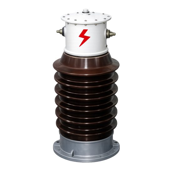
The CT-35K is a medium-voltage cast-resin current transformer engineered for reliable operation in 33kV (IEC) / 35kV (domestic) power systems. Designed in strict accordance with IEC 61869-2 and GB/T 20840.2, this instrument transformer provides galvanic isolation between high-voltage primary conductors and low-voltage secondary instrumentation circuits, enabling accurate current measurement while ensuring personnel and equipment safety. Its robust construction supports both indoor switchgear integration and outdoor pole-mounted or substation applications.
Operating Principle of Cast-Resin Insulation
Cast-resin insulation in the CT-35K utilizes vacuum pressure impregnation (VPI) epoxy resin technology to encapsulate the primary winding and magnetic core assembly. This process eliminates air voids and moisture ingress pathways, resulting in superior dielectric strength and long-term environmental resistance. The resin matrix exhibits a relative permittivity (εr) of approximately 4.2 and volume resistivity exceeding 1×10¹⁴ Ω·cm at 20°C. Unlike oil-filled alternatives, the solid dielectric system requires no maintenance, poses no fire hazard, and remains stable across thermal cycling from –40°C to +70°C ambient conditions. The homogeneous insulation structure ensures uniform electric field distribution, minimizing partial discharge activity—typically below 10 pC at 1.2 × Um/√3 during factory testing.
Advantages Over Oil-Immersed Designs
Compared to traditional oil-immersed current transformers, the CT-35K’s cast-resin design offers significant operational and safety benefits. It eliminates risks associated with oil leakage, flammability, and environmental contamination. The solid insulation enables compact physical dimensions—reducing footprint by up to 30%—which is critical in space-constrained indoor substations. Additionally, cast-resin units exhibit faster thermal response due to higher thermal conductivity (~0.2 W/m·K vs. ~0.12 W/m·K for mineral oil), improving transient performance during fault conditions. Maintenance costs are substantially lower over the 25–30 year service life, as no oil sampling, degassing, or tank inspections are required. The CT-35K also complies with RoHS and REACH directives, reflecting modern sustainability requirements in electrical infrastructure.
Typical Applications Overview
The CT-35K serves dual roles in metering and protection circuits across utility and industrial networks. In revenue metering applications, it delivers Class 0.2S or 0.5S accuracy under load currents from 5% to 120% of rated primary current. For protection, it maintains defined error limits up to 20× rated current (e.g., 5P20 or 10P20 classes), ensuring reliable relay operation during short-circuit events. Common deployment scenarios include 33kV ring main units (RMUs), outdoor pad-mounted transformers, wind farm collector substations, and mining power distribution centers. Its IP54-rated terminal box accommodates standard 4 mm² or 6 mm² copper conductors with screw-type terminals, facilitating secure secondary connections resistant to vibration and thermal expansion.
Technical Specifications
The CT-35K is engineered to meet stringent electrical and mechanical performance criteria under standardized service conditions. All parameters align with IEC 61869-2:2012 and GB/T 20840.2-2014, ensuring interoperability in global power systems.
| Parameter | Value |
|---|---|
| Rated System Voltage (Um) | 33 kV (IEC) / 35 kV (Domestic) |
| Rated Primary Current (Ip) | 50 A to 3150 A (standard steps) |
| Rated Secondary Current (Is) | 1 A or 5 A |
| Current Ratio | Customizable (e.g., 600/5, 1200/1) |
| Metering Accuracy Class | 0.2S, 0.5S |
| Protection Accuracy Class | 5P10, 5P20, 10P10, 10P20 |
| Rated Output (Burden) | 5 VA to 30 VA (per class) |
| Insulation Level (LI/AC) | 170 kV / 70 kV (1 min) |
| Short-Time Thermal Current | 25 kA for 1 s (at Ip = 1250 A) |
| Dynamic Withstand Current | 62.5 kA peak |
| Core Material | Grain-Oriented Electrical Steel (GOES), 0.27 mm thickness |
| Insulation System | VPI Epoxy Resin, UL 94 V-0 rated |
| Ambient Temperature Range | –40°C to +40°C (max. 24-h avg. +35°C) |
| Altitude Limit | ≤ 1000 m (derating required above) |
| Humidity | Relative humidity ≤ 95% (non-condensing) |
Standard Service Conditions
The CT-35K is rated for continuous operation under IEC 60060-1 standard atmospheric conditions: ambient temperature between –40°C and +40°C, with a 24-hour average not exceeding +35°C. Relative humidity may reach 95% provided condensation does not occur on the housing surface. Installation altitude must not exceed 1000 meters above sea level; for sites between 1000 m and 3000 m, voltage withstand values must be derated by 1% per 100 m increment. The transformer is designed for three-phase systems with symmetrical fault currents and assumes sinusoidal waveforms with total harmonic distortion (THD) ≤ 5%. Operation in polluted environments (e.g., coastal or industrial zones) is supported due to the hydrophobic nature of the epoxy resin and creepage distance of ≥ 25 mm/kV (phase-to-ground).
Accuracy and Burden Characteristics
Metering accuracy classes 0.2S and 0.5S guarantee composite error within ±0.2% and ±0.5%, respectively, at 100% and 120% of rated current, and within ±0.35% and ±0.75% at 20% load. At 5% of rated current, errors remain within ±1.5% (0.2S) and ±3.0% (0.5S), critical for low-load billing scenarios. Protection classes (e.g., 5P20) ensure that the composite error does not exceed 5% when subjected to 20 times rated current with a specified burden (e.g., 15 VA). The secondary winding is optimized for minimal phase displacement—typically < ±10 minutes for metering classes—ensuring compatibility with vector-based energy meters and synchrophasor applications. Burden tolerance is ±10% of nominal value; exceeding this may degrade accuracy or cause saturation during faults.
Typical Applications
The CT-35K’s dual-certification and robust design enable deployment across diverse power infrastructure segments requiring precise current transformation at 33kV system voltage.
Substation Secondary Metering
In utility-owned 33kV/11kV distribution substations, the CT-35K provides revenue-grade current signals to kWh meters compliant with IEC 62053-22. Installed on incomer or feeder circuits, it interfaces with Class 0.2S meters to capture energy consumption data with <0.3% uncertainty under normal load profiles. The transformer’s low phase error (<±5 minutes at 100% In) ensures accurate reactive energy measurement, essential for power factor billing. Its cast-resin housing resists UV degradation and salt fog, making it suitable for coastal substations where metal corrosion compromises oil-filled units. Secondary wiring connects directly to meter cabinets via shielded twisted-pair cables, minimizing electromagnetic interference from adjacent switchgear operations.
Industrial Power Distribution
Large manufacturing facilities—such as steel mills, chemical plants, and data centers—utilize the CT-35K on 33kV primary feeders to monitor load profiles and protect critical motors or transformers. In arc furnace installations, the CT withstands high harmonic content (up to 15% THD) without significant accuracy drift due to its GOES core’s low hysteresis loss. Protection-class windings (e.g., 10P20) feed digital relays like the SEL-751, enabling fast tripping during phase-to-phase faults. The unit’s IP54 terminal box prevents dust ingress in harsh environments, while its non-flammable construction meets NFPA 70E arc-flash safety requirements. Multiple ratio taps allow future load growth without hardware replacement.
Renewable Energy Integration
Wind and solar farms employ the CT-35K at the 33kV collector substation level to interface generation output with SCADA systems and revenue meters. During cloud transients or wind gusts, rapid current fluctuations (di/dt up to 100 A/ms) are accurately tracked thanks to the core’s high permeability (μr > 40,000) and low remanence (<0.8 T). The transformer supports bidirectional power flow measurement, crucial for grid-support functions like reactive power injection. Its outdoor rating (–40°C startup) ensures reliability in extreme climates—from Scandinavian wind parks to Middle Eastern solar arrays. Compliance with IEC 61869-2 facilitates interconnection approval from grid operators like National Grid or CAISO.
Rural and Suburban Distribution Networks
In rural electrification projects, the CT-35K is mounted on pole-top platforms or pad-mounted switchgear to provide metering for agricultural pumps or village microgrids. Its lightweight design (≈45 kg) simplifies helicopter or manual installation in remote areas lacking road access. The 5 A secondary output matches legacy electromechanical relays still prevalent in developing regions, while 1 A variants reduce copper losses in long cable runs (>100 m). Theft-resistant terminal boxes with tamper-evident seals deter unauthorized bypassing—a common issue in unmetered regions. With a 30-year design life and zero maintenance, it offers lower total cost of ownership than oil-filled alternatives in low-budget deployments.
Compliance with International Standards
The CT-35K is certified to both international and Chinese national standards, ensuring global market acceptance and technical interoperability.
IEC 61869-2 Compliance Details
IEC 61869-2:2012 defines performance, testing, and marking requirements for inductive current transformers. The CT-35K meets all clauses, including Clause 6 (rated values), Clause 7 (accuracy requirements), and Clause 12 (type tests). Key compliance aspects include: (1) insulation coordination per IEC 60071-1, with lightning impulse withstand of 170 kV peak; (2) temperature rise limits of ≤60 K for windings (measured by resistance method); (3) short-circuit withstand verified per IEC 60044-1 Annex B; and (4) partial discharge levels <10 pC at 1.2 × Um/√3. Factory routine tests include polarity verification, turns ratio check (±0.25% tolerance), and power frequency withstand (70 kV rms for 1 min). Each unit bears a permanent nameplate with IEC-compliant markings: rated voltage, ratio, accuracy class, burden, and manufacturer ID.
GB/T 20840.2 Alignment
GB/T 20840.2-2014 is China’s national adoption of IEC 61869-2, with minor deviations. The CT-35K satisfies all mandatory GB clauses, including enhanced seismic requirements (horizontal acceleration 0.3g) and stricter pollution degree classification (III instead of II). While IEC permits 5P/10P protection classes, GB/T additionally recognizes 3P classes for specific relay coordination schemes. The domestic standard mandates a minimum short-time thermal current of 25 kA/1s for 35kV systems—exactly matched by the CT-35K. Chinese grid codes (e.g., Q/GDW 13091.2) require secondary terminal boxes to include grounding lugs and cable clamps, which are integrated into the CT-35K’s design. Certification is issued by CEPREI or SGS China after witnessing type tests at accredited labs.
Key Differences Between IEC and Domestic Standards
Although harmonized, IEC 61869-2 and GB/T 20840.2 exhibit nuanced differences affecting procurement and testing. IEC uses 33kV as the standard highest voltage for equipment (Um), whereas GB references 35kV system voltage—though insulation levels remain identical (LI 170 kV / AC 70 kV). GB/T imposes tighter tolerances on ratio error at 1% of rated current for metering classes (±3.0% vs. IEC’s ±6.0%), demanding higher core quality. Environmental testing under GB includes salt spray exposure (96 hours per GB/T 2423.17), absent in IEC. Additionally, Chinese utilities often require dual secondary windings (one for metering, one for protection) as standard, while IEC treats this as optional. The CT-35K accommodates both configurations, ensuring seamless deployment in export and domestic markets.
On-Site Testing Procedures
Post-installation verification ensures the CT-35K performs within specification before energization. All tests follow IEC 61869-2 Annex D and IEEE C57.13 guidelines.
Insulation Resistance Test
Measure insulation resistance between primary winding and ground, and between secondary windings and ground, using a 2500 V DC megohmmeter. Acceptance criterion: ≥1000 MΩ at 20°C. Correct for temperature using RT2 = RT1 × 2(T1–T2)/10. Low readings (<100 MΩ) indicate moisture ingress or resin cracking—requiring drying or replacement. Perform before and after high-voltage tests to detect insulation damage.
Turns Ratio Test
Apply a low-voltage AC source (50/60 Hz) to the primary and measure secondary voltage. Calculate actual ratio as Vp/Vs. Compare to nameplate ratio; tolerance must be within ±0.25% for metering classes and ±0.5% for protection classes. Use a precision ratio bridge (e.g., Omicron CT Analyzer) for accuracy. Deviations >1% suggest turn-to-turn shorts or incorrect tap selection.
Polarity Test
Verify reducing polarity per IEC 61869-2 Figure 4. Connect a 1.5 V DC battery momentarily across primary terminals (P1 to P2). Observe secondary voltage on a DC voltmeter: a positive kick at S1 confirms correct polarity. Incorrect polarity causes 180° phase reversal, leading to metering errors or relay misoperation. Repeat three times to eliminate contact bounce artifacts.
Power Frequency Withstand Voltage Test
Apply 70 kV rms (50 Hz) between primary and ground for 1 minute. Ramp up at 2 kV/s, hold, then ramp down. No flashover or disruptive discharge is permitted. Use a calibrated test transformer with overcurrent trip set at 2× capacitive current (typically 10–20 mA). Conduct in dry conditions (RH <80%) with clean bushings. Failure indicates insulation defects from shipping damage or casting voids.
Short-Circuit Test (for CT)
Inject 10× rated secondary current (e.g., 50 A for 5 A CT) into the secondary winding with primary shorted. Measure voltage drop across secondary; calculate impedance Z = V/I. Compare to factory data—deviation >10% suggests core saturation or winding deformation. This test validates thermal stability under fault conditions and verifies burden compatibility with connected relays.
Preventive Maintenance Guide
Although cast-resin CTs require minimal maintenance, periodic checks extend service life and prevent unexpected failures.
Periodic Inspection Protocol
Conduct annual visual inspections: check for cracks, tracking, or discoloration on the resin housing; verify terminal tightness (torque: 2.5 N·m for M6 screws); inspect gasket integrity on the terminal box; and confirm grounding continuity (<0.1 Ω resistance). Clean surfaces with isopropyl alcohol if contaminated with salt or dust. In high-pollution areas (e.g., cement plants), increase frequency to semi-annual. Document findings in asset management systems to trend degradation.
Maintenance Intervals and Fault Diagnosis
Every 5 years, perform electrical tests: insulation resistance, turns ratio, and excitation curve comparison to baseline. A rising excitation current at 50% knee-point voltage indicates core aging or moisture absorption. Common faults include: (1) open secondary circuit—causing dangerous overvoltage (>10 kV)—detected by infinite insulation resistance; (2) ratio drift from mechanical shock during transport; (3) terminal corrosion increasing contact resistance. Replace units exhibiting >2% ratio error or PD >50 pC during on-site testing.
| Maintenance Interval | Activities |
|---|---|
| Annual | Visual inspection, torque check, cleaning |
| 5-Year | Electrical tests (IR, ratio, excitation), PD measurement if available |
| After Major Fault | Full electrical test suite, mechanical integrity assessment |
Conclusion
The CT-35K 33kV cast-resin current transformer represents a technically mature solution for metering and protection in modern medium-voltage networks. Its compliance with IEC 61869-2 and GB/T 20840.2 ensures global acceptance, while the VPI epoxy resin insulation system delivers unmatched reliability in both indoor and outdoor environments. Key advantages include maintenance-free operation, fire safety, compact size, and precise performance across wide current ranges—from 5% of rated load for billing accuracy to 20× overload for dependable relay coordination. The use of grain-oriented electrical steel minimizes core losses and enhances linearity, critical for harmonic-rich applications like renewable integration. With a design life of 25–30 years and robustness against thermal cycling, pollution, and mechanical stress, the CT-35K reduces lifecycle costs while meeting the stringent accuracy and safety demands of contemporary power systems. Utilities and industrial operators can deploy this transformer with confidence, knowing it has undergone rigorous type and routine testing per international protocols. As grids evolve toward digitalization and distributed generation, the CT-35K’s stable analog output remains foundational for accurate monitoring, control, and revenue assurance.
Q1: Can the CT-35K be used in 35kV systems despite its 33kV IEC rating?
Yes. The 33kV designation refers to the IEC standard highest voltage for equipment (Um). It is fully compatible with 35kV nominal systems, as both share identical insulation levels (LI 170 kV / AC 70 kV).
Q2: What is the maximum altitude for installation without derating?
1000 meters above sea level. Above this, the power frequency and lightning impulse withstand voltages must be reduced by 1% per 100 m increment.
Q3: Does the CT-35K support multiple secondary windings?
Yes. Standard configurations include single or dual secondaries (e.g., 0.2S/5P20), allowing independent metering and protection circuits.
Q4: What is the typical partial discharge level at factory test?
Less than 10 picocoulombs (pC) at 1.2 × Um/√3 (22.9 kV), measured per IEC 60270.
Q5: Is the terminal box suitable for direct burial applications?
No. The IP54 rating protects against dust and water jets but is not rated for submersion. For underground vaults, install in a sealed enclosure.
Q6: What core material is used, and why?
Grain-oriented electrical steel (GOES), 0.27 mm thick. This material offers high permeability and low core loss, essential for accuracy and thermal stability.
Q7: How is polarity marked on the CT-35K?
Primary terminals are labeled P1 (line side) and P2 (load side). Secondary terminals are S1 (corresponding to P1) and S2, with S1 typically grounded per IEC 61869-2 reducing polarity convention.
Q8: What is the short-circuit withstand capability?
Thermal: 25 kA for 1 second. Dynamic: 62.5 kA peak, verified per IEC 61869-2 Clause 12.6.