Article Content
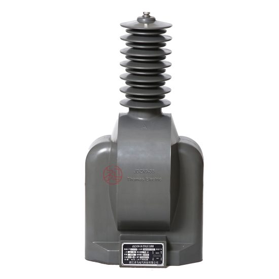
Outdoor 33kV Cast-Resin Voltage Transformer JDZW-35 – IEC 61869-3 Compliant
Introduction to the JDZW-35 Voltage Transformer
The JDZW-35 is a single-phase, outdoor-rated cast-resin voltage transformer (VT) engineered for precise voltage measurement and dependable operation in 33 kV (IEC) / 35 kV (domestic) medium-voltage power systems. Unlike legacy oil-immersed designs, this instrument transformer employs vacuum pressure impregnated (VPI) epoxy resin insulation technology, offering superior dielectric strength, environmental resilience, and maintenance-free operation over its service life. The JDZW-35 serves critical roles in revenue metering, protective relaying, and system monitoring across utility substations, industrial plants, and renewable energy interconnection points.
Operating Principle of Cast-Resin Insulation
Cast-resin insulation in the JDZW-35 utilizes a thermosetting epoxy resin matrix that fully encapsulates the primary and secondary windings along with the magnetic core. During manufacturing, the assembly undergoes vacuum degassing followed by pressure impregnation to eliminate air voids—a common failure point in oil-filled units. This monolithic structure provides uniform electric field distribution and high partial discharge inception voltage (>20 kV at 50 Hz). The resin’s thermal class is F (155°C), enabling continuous operation under load without degradation. Dielectric tests per IEC 61869-3 confirm a withstand voltage of 70 kV (rms, 1 min) between windings and ground, with lightning impulse withstand rated at 170 kV (peak). The absence of flammable oil eliminates fire hazards and simplifies compliance with environmental regulations such as RoHS and REACH.
Advantages Over Oil-Immersed Designs
Compared to traditional oil-immersed VTs, the JDZW-35’s cast-resin construction delivers significant operational advantages. First, it requires no periodic oil sampling, gas analysis, or tank sealing maintenance—reducing lifecycle costs by up to 40% over 25 years. Second, the solid insulation exhibits negligible aging under thermal cycling (–40°C to +40°C ambient), whereas oil viscosity changes can impair performance in extreme climates. Third, the compact, hermetically sealed design resists moisture ingress (IP54 rating), making it ideal for coastal or high-humidity regions where oil units suffer from water contamination. Finally, the unit’s lighter weight (~120 kg vs. ~180 kg for equivalent oil type) eases transportation and mounting on pole-top or busbar structures. These attributes make the JDZW-35 particularly suited for remote or unmanned substations where reliability and minimal intervention are paramount.
Typical Applications Overview
The JDZW-35 is deployed wherever accurate voltage transformation from 33/√3 kV to standard secondary values (e.g., 100/√3 V or 110/√3 V) is required. Primary use cases include 35 kV distribution substations feeding urban grids, industrial facilities with large motor loads requiring undervoltage protection, and solar/wind farms interfacing with the transmission network. Its dual-winding configuration supports simultaneous connection to metering (Class 0.2 or 0.5) and protection (Class 3P or 6P) circuits. For example, in a 35/10 kV step-down substation, two JDZW-35 units (connected phase-to-ground) provide inputs to a digital multifunction relay for earth-fault detection while feeding kWh meters for billing. The transformer’s low burden error (<±0.2% at 25–100% rated load) ensures compliance with revenue-grade accuracy mandates under GB/T 17215.
Technical Specifications
The JDZW-35 adheres strictly to IEC 61869-3 and GB/T 20840.3, with key parameters calibrated for 33 kV system voltage (corresponding to 35 kV nominal domestic networks). All electrical characteristics are validated under standard reference conditions per IEC 60060.
| Parameter | Value |
|---|---|
| System Voltage (IEC) | 33 kV |
| Nominal System Voltage (Domestic) | 35 kV |
| Primary Voltage | 33/√3 kV (phase-to-ground) |
| Secondary Voltages | 100/√3 V, 110/√3 V (standard); custom ratios available |
| Rated Output (per winding) | 30 VA (metering), 50 VA (protection) |
| Accuracy Class | Metering: 0.2, 0.5; Protection: 3P, 6P |
| Insulation Level (LI/AC) | 170/70 kV |
| Short-Time Thermal Withstand | 1.2 × In for 1 s (secondary short-circuit) |
| Ambient Temperature Range | –40°C to +40°C |
| Altitude Limit | ≤1000 m (derating required above) |
| Relative Humidity | ≤95% (non-condensing) |
| Core Material | Grain-Oriented Electrical Steel (GOES), 0.27 mm thickness |
| Insulation System | VPI Epoxy Resin, Class F (155°C) |
| Weight | Approx. 120 kg |
| Mounting | Flange base (M16 bolts, PCD 220 mm) |
Standard Service Conditions
The JDZW-35 is rated for outdoor installation under IEC 60060 standard atmospheric conditions: ambient temperature from –40°C to +40°C, daily average not exceeding +35°C. Relative humidity may reach 95% provided condensation does not occur on the housing. At altitudes above 1000 m, the dielectric strength must be derated by 1% per 100 m increment due to reduced air density; for instance, at 2000 m, the power frequency withstand voltage becomes 63 kV instead of 70 kV. The transformer is designed for continuous operation at 1.2 × Un (39.6 kV) for up to 8 hours without exceeding thermal limits. Pollution severity is classified as III (medium) per IEC 60815, with creepage distance ≥25 mm/kV (minimum 825 mm for 33 kV).
Electrical Performance Parameters
Under rated load (30 VA at cos φ = 0.8 lagging), the JDZW-35 achieves ratio error within ±0.2% and phase displacement ≤10 minutes for Class 0.2 accuracy. For protection applications (Class 3P), errors remain within ±3% up to 5 × rated voltage during transient overvoltages. The magnetizing current is ≤0.5% of rated primary current at 1.9 × Un, ensuring stable operation during ferroresonance events. Burden compatibility extends from 2.5 VA to 100% of rated output without exceeding accuracy limits. Temperature rise tests confirm winding hot-spot temperatures stay below 100 K above ambient under full load, well within Class F insulation margins. These parameters are verified during type testing per Clause 7 of IEC 61869-3.
Typical Applications
The JDZW-35’s robust design and dual-accuracy capability enable deployment across diverse power infrastructure scenarios.
Substation Secondary Metering
In 35 kV/10 kV distribution substations, the JDZW-35 provides the voltage reference for revenue metering systems. Two units (phases A and C) are typically connected in open-delta configuration to feed three-phase kWh meters compliant with DL/T 614. The transformer’s Class 0.2 accuracy ensures billing precision even under light-load conditions (down to 1% of rated current). For example, in a municipal utility substation serving 10,000 residential customers, the JDZW-35’s low phase error (<5 arcmin) prevents cumulative billing discrepancies exceeding regulatory thresholds (±0.5%). Its cast-resin housing withstands electromagnetic interference from nearby switchgear, maintaining signal integrity for AMI (Advanced Metering Infrastructure) systems.
Industrial Power Distribution
Large industrial complexes—such as steel mills or chemical plants—use the JDZW-35 for both process control and protection. Here, the VT supplies voltage signals to motor protection relays (e.g., SEL-710) that detect undervoltage, overvoltage, and phase imbalance. The Class 3P winding handles fault currents during short circuits, while the metering winding interfaces with SCADA for energy management. In a cement plant with 35 kV induction motors, the JDZW-35’s thermal stability prevents accuracy drift during frequent motor startups, which cause voltage sags to 70% Un. The unit’s IP54 rating also resists dust ingress in harsh environments, eliminating the need for protective enclosures.
Renewable Energy Integration
Solar photovoltaic and wind farms connecting to 35 kV grids rely on the JDZW-35 for grid-code compliance monitoring. The VT feeds synchrophasor measurement units (PMUs) that verify voltage magnitude and angle per GB/T 19964. During cloud-induced irradiance fluctuations, the JDZW-35 maintains ratio stability within ±0.3% despite rapid voltage changes (dv/dt up to 5 kV/s). Its low remanence (<0.2 T) prevents core saturation during islanding events, ensuring accurate detection of anti-islanding protection schemes. In a 50 MW solar farm in Gansu Province, dual JDZW-35 units enabled precise reactive power control to maintain grid voltage within ±5% tolerance.
Rural and Suburban Distribution Networks
For remote rural electrification projects, the JDZW-35’s maintenance-free operation reduces O&M costs significantly. Mounted on pole-top structures, it supplies voltage to single-phase meters in villages with limited technical staff. The transformer’s wide temperature tolerance (–40°C) ensures functionality in northern China winters, while UV-resistant resin prevents surface cracking under intense sunlight. In suburban ring-main units, the JDZW-35 enables automated fault location by providing synchronized voltage waveforms to distribution automation terminals (DTUs). Its compact size allows installation in space-constrained cabinets without compromising safety clearances.
Compliance with International Standards
The JDZW-35 is certified to both international and Chinese national standards, ensuring interoperability and regulatory acceptance.
IEC 61869-3 Compliance Details
IEC 61869-3:2011 governs the performance, testing, and safety requirements for inductive voltage transformers. The JDZW-35 meets all mandatory clauses, including:
– Accuracy verification under burdens from 25% to 100% of rated VA (Clause 6.3)
– Temperature rise limits not exceeding 60 K for resin-insulated windings (Clause 7.2)
– Partial discharge levels <10 pC at 1.2 × Un/√3 (Clause 8.4)
- Short-circuit withstand capability per Annex D
Type tests conducted by third-party labs (e.g., KEMA) confirm compliance, with test reports available upon request. The standard’s emphasis on transient performance ensures the JDZW-35 operates reliably during switching surges and lightning events.
GB/T 20840.3 Alignment
GB/T 20840.3-2013 is the Chinese adoption of IEC 61869-3, with minor modifications for domestic grid conditions. Key alignments include:
– Identical accuracy classes (0.2, 0.5, 3P, 6P)
– Same insulation levels (170/70 kV for 35 kV class)
– Equivalent short-time thermal withstand requirements
However, GB/T 20840.3 mandates additional tests for pollution performance in heavy industrial zones (creepage distance ≥31 mm/kV) and specifies stricter ratio error limits at 1% load for metering classes. The JDZW-35 exceeds these requirements through optimized core geometry and precision winding techniques.
Key Differences Between IEC and Domestic Standards
While harmonized, subtle differences exist:
1. **Voltage Reference**: IEC uses 33 kV as the standard system voltage for 35 kV class equipment, whereas Chinese utilities specify 35 kV nominal. The JDZW-35’s primary is rated 33/√3 kV but tested at 35/√3 kV for domestic certification.
2. **Burden Definition**: GB/T 20840.3 defines rated burden at cos φ = 0.8 lagging, matching IEC, but adds optional leading power factor tests for capacitor-connected loads.
3. **Marking Requirements**: Chinese standards require bilingual (Chinese/English) nameplates with CCC certification marks, while IEC permits English-only labeling.
These distinctions are addressed during dual-certification processes, ensuring the JDZW-35 meets both export and domestic market needs.
On-Site Testing Procedures
Post-installation verification ensures the JDZW-35 performs within specifications before energization.
Insulation Resistance Test
Using a 2500 V DC megohmmeter, measure insulation resistance between:
– Primary winding and ground
– Secondary windings and ground
– Primary and secondary windings
Acceptance criteria: ≥1000 MΩ at 20°C. Correct for temperature using Rt = R20 × 1.5(20–t)/10. Values below 500 MΩ indicate moisture ingress or resin cracking, requiring drying or replacement. Perform before and after power frequency withstand tests to detect insulation degradation.
Turns Ratio Test
Apply 100–200 V AC to the primary winding and measure secondary voltage with a calibrated voltmeter (accuracy class 0.1). Calculate actual ratio: K = Up/Us. Compare to nameplate value (e.g., 33000/√3 : 100/√3 = 330:1). Tolerance: ±0.2% for metering class, ±3% for protection class. Use a dedicated turns ratio tester (e.g., Omicron CT Analyzer) for automated comparison. Significant deviation suggests winding shorts or incorrect tap selection.
Polarity Test
Verify reducing polarity per IEC 61869-3 Figure 3. Connect a 6–12 V battery momentarily between primary terminals H1 (+) and H2 (–). Observe secondary voltage polarity with a DC millivoltmeter: X1 should show positive deflection when H1 is energized. Incorrect polarity causes 180° phase shift, leading to metering errors or relay misoperation. Document results with oscillograms if digital relays are connected.
Power Frequency Withstand Voltage Test
Apply 70 kV rms (50 Hz) for 1 minute between primary and ground, and between primary and secondaries shorted together. Ramp voltage at 1–2 kV/s to avoid transient overvoltages. Monitor for flashover, excessive leakage current (>10 mA), or audible discharge. Reduce voltage gradually post-test. This validates insulation integrity after transport stresses. Do not perform if ambient humidity exceeds 80% to prevent surface tracking.
Open-Circuit Characteristic Test
With secondaries open, apply variable voltage (0–1.9 × Un) to the primary and record excitation current. Plot Iexc vs. Up. The knee point should occur above 1.5 × Un, indicating adequate core margin against saturation. At 1.9 × Un, Iexc must be ≤0.5% of rated primary current. Excessive magnetizing current suggests core lamination damage or shorted turns, compromising accuracy during overvoltage events.
Preventive Maintenance Guide
Although cast-resin VTs require minimal maintenance, periodic checks extend service life and prevent failures.
Periodic Inspection Schedule
Conduct visual and electrical inspections annually:
– Check for surface cracks, tracking, or discoloration on resin housing
– Verify terminal tightness (torque: 25 N·m for M12 studs)
– Clean porcelain sheds with deionized water if salt/fog contamination is present
– Measure insulation resistance (baseline comparison)
Biannually, inspect mounting hardware for corrosion, especially in coastal areas. After severe weather (lightning strikes, typhoons), perform immediate ratio and polarity tests. Maintain logs of all readings to trend degradation—e.g., insulation resistance declining >20% year-over-year warrants further investigation.
Maintenance Intervals and Fault Diagnosis
| Interval | Action | Fault Indicators |
|---|---|---|
| Annual | Visual inspection, IR scan, insulation resistance | Cracks, hot spots (>10 K above ambient), IR <500 MΩ |
| 5-Year | Full electrical tests (ratio, polarity, withstand) | Ratio error >0.5%, polarity reversal, flashover |
| After Fault | Excitation curve, partial discharge (if available) | Knee point shift, PD >20 pC |
Common failure modes include:
– **Moisture ingress**: Causes reduced IR and increased dielectric loss; remediate with oven drying at 80°C for 24 h if early-stage.
– **Terminal corrosion**: Leads to contact resistance rise; clean with abrasive pad and apply antioxidant compound.
– **Core damage**: From mechanical shock during shipping; diagnosed via elevated excitation current.
Replacement is recommended if any parameter exceeds IEC 61869-3 limits after corrective actions.
Conclusion
The JDZW-35 cast-resin voltage transformer represents a technically mature solution for 33 kV (IEC) / 35 kV (domestic) outdoor applications demanding high accuracy, long-term reliability, and minimal maintenance. Its VPI epoxy resin insulation system eliminates the fire, environmental, and operational drawbacks of oil-filled alternatives while delivering superior dielectric performance and thermal stability. Compliance with both IEC 61869-3 and GB/T 20840.3 ensures global acceptance and seamless integration into modern digital substations. With a design life of 25–30 years under standard service conditions, the JDZW-35 provides exceptional lifecycle value for utilities and industrial operators. Its dual-winding architecture supports concurrent metering (Class 0.2/0.5) and protection (Class 3P/6P) functions without compromise, while rigorous factory and field testing protocols guarantee performance consistency. As power systems evolve toward smarter, more resilient architectures, the JDZW-35’s robust engineering and standards-aligned design position it as a cornerstone component for accurate voltage transformation in medium-voltage networks worldwide.