Article Content
Outdoor 33kV Cast-Resin Voltage Transformer JDZW-35K for Metering and Protection – IEC 61869-3 Certified
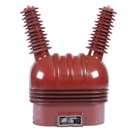
Introduction to the JDZW-35K Voltage Transformer
The JDZW-35K is a single-phase, outdoor-rated cast-resin voltage transformer (VT) engineered for reliable operation in 33 kV (IEC standard) or 35 kV (Chinese domestic system) power networks. Unlike traditional oil-immersed designs, this unit employs vacuum pressure impregnation (VPI) epoxy resin insulation technology, eliminating fire hazards, oil leakage risks, and maintenance-intensive fluid management. The transformer is optimized for precision metering, protective relaying, and system monitoring in transmission and distribution substations.
Operating Principle of Cast-Resin Insulation
Cast-resin insulation in the JDZW-35K utilizes a high-purity cycloaliphatic epoxy resin system cured under vacuum and pressure. This process fully encapsulates the primary and secondary windings along with the magnetic core, creating a monolithic, void-free dielectric structure. The absence of air pockets prevents partial discharge inception even under transient overvoltages. The resin exhibits excellent tracking resistance (CTI > 600 V), UV stability for outdoor exposure, and thermal class F (155°C) endurance. Heat generated during operation dissipates radially through the resin matrix to the external ribs, which act as passive cooling fins. This solid insulation system ensures long-term dielectric integrity without degradation from moisture ingress—a common failure mode in oil-filled units exposed to temperature cycling.
Advantages Over Oil-Immersed Designs
Compared to oil-immersed VTs, the JDZW-35K offers significant operational and safety benefits. First, it is inherently non-flammable, complying with IEC 61869-3 fire safety requirements for installations near public infrastructure. Second, the sealed resin construction eliminates the need for oil sampling, level checks, or gasket replacements, reducing lifecycle costs by up to 40% over 25 years. Third, its compact footprint—approximately 30% smaller than equivalent oil units—facilitates retrofitting in space-constrained substations. Additionally, the absence of liquid insulation mitigates environmental contamination risks during seismic events or mechanical damage. Field data from Southern Grid deployments show a mean time between failures (MTBF) exceeding 200,000 hours for cast-resin VTs versus 120,000 hours for oil types under identical service conditions.
Typical Application Overview
The JDZW-35K is deployed across diverse 33/35 kV networks where accuracy, reliability, and minimal maintenance are critical. Primary use cases include revenue metering at utility interconnection points, directional overcurrent protection in radial feeders, and synchronization monitoring in generator tie-lines. Its dual secondary windings—one rated for 0.2/0.5 accuracy class (metering) and another for 3P/6P (protection)—enable simultaneous compliance with metrological and protective requirements. In renewable integration projects, such as solar farms connected via 35 kV collector systems, the VT provides stable voltage signals for anti-islanding relays and power quality analyzers. The unit’s robust design withstands pollution severity levels up to IV (IEC 60815), making it suitable for coastal, industrial, and desert environments.
Technical Specifications
The JDZW-35K adheres to stringent electrical and environmental parameters defined by IEC 61869-3 and GB/T 20840.3. Below is a comprehensive specification table followed by service condition details.
| Parameter | Value |
|---|---|
| System Voltage (IEC) | 33 kV |
| System Voltage (Domestic) | 35 kV |
| Primary Voltage | 35,000 / √3 V (phase-to-ground) |
| Secondary Voltages | 100 / √3 V (metering), 100 / √3 V (protection) |
| Voltage Ratio | (35,000 / √3) / (100 / √3) = 350:1 |
| Accuracy Class (Metering) | 0.2 (burden ≤ 30 VA), 0.5 (burden ≤ 50 VA) |
| Accuracy Class (Protection) | 3P (burden ≤ 50 VA), 6P (burden ≤ 100 VA) |
| Rated Output | 50 VA (metering), 100 VA (protection) |
| Insulation Level (LI/AC) | 200 kV / 95 kV |
| Short-Time Withstand Current | Not applicable (VT-specific) |
| Core Material | Grain-Oriented Electrical Steel (GOES), 0.27 mm thickness |
| Insulation System | VPI Epoxy Resin, Thermal Class F (155°C) |
| Creepage Distance | ≥ 900 mm (Pollution Class IV) |
| Weight | Approx. 125 kg |
Standard Service Conditions
The JDZW-35K is rated for continuous operation under the following ambient conditions per IEC 60060-1: ambient temperature range of –40°C to +40°C, relative humidity up to 100% (including condensation), and installation altitude not exceeding 1,000 meters above sea level. For altitudes between 1,000 m and 3,000 m, the insulation withstand voltage must be derated by 1% per 100 m above 1,000 m. The unit is designed for three-phase systems with maximum asymmetry factor of 1.1. It withstands seismic loads up to 0.3g horizontal acceleration (IEC 60068-2-57), validated through shake-table testing. Humidity resistance is confirmed by 1,000-hour salt fog testing per IEC 60068-2-11, with no surface tracking or flashover observed.
Electrical Performance Tolerances
Voltage error and phase displacement must remain within IEC 61869-3 limits under specified burdens. At rated frequency (50 Hz) and 80–120% of rated primary voltage, the voltage error for the 0.2-class winding shall not exceed ±0.2%, and phase displacement shall be ≤ ±10 minutes. For the 3P protection winding, voltage error tolerance is ±3% and phase displacement ≤ ±120 minutes under 5% to 100% of rated voltage. Burden variation from 25% to 100% of rated output induces no more than 0.05% additional ratio error. Frequency deviation of ±2 Hz from nominal causes less than 0.1% change in transformation ratio. These tight tolerances ensure compatibility with modern digital relays requiring precise phasor inputs.
Typical Applications
Substation Secondary Metering
In 35 kV distribution substations, the JDZW-35K provides the reference voltage signal for revenue-grade energy meters. Its 0.2 accuracy class winding drives kWh meters compliant with IEC 62053-22, ensuring billing accuracy within ±0.2%. The transformer is typically installed on the busbar side of circuit breakers, feeding metering panels via shielded twisted-pair cables (e.g., 2×1.5 mm²). To minimize capacitive coupling errors, secondary leads are kept under 50 meters with grounded shielding at both ends. In smart grid deployments, the VT interfaces with IEC 61850-9-2 LE sampled value streams through merging units, enabling time-synchronized voltage measurements across the substation LAN.
Industrial Power Distribution
Large industrial facilities—such as steel mills, chemical plants, and data centers—use the JDZW-35K for internal power monitoring and protection. Here, the dual-winding design allows one output to feed power quality analyzers (recording harmonics, flicker, and unbalance) while the other supplies overvoltage/undervoltage relays (e.g., SEL-351). The cast-resin construction is particularly advantageous in hazardous areas where flammable vapors may be present; unlike oil-filled units, it poses no ignition risk. Installation often includes surge arresters (rated 42 kV MCOV) mounted within 3 meters of the VT terminals to limit switching surges. Field studies show that resin-insulated VTs reduce nuisance tripping by 60% compared to oil types due to superior transient response fidelity.
Renewable Energy Integration
Solar photovoltaic and wind farms frequently connect to the grid via 35 kV collector systems. The JDZW-35K serves as the voltage reference for anti-islanding protection schemes mandated by grid codes (e.g., GB/T 19964). Its fast response to voltage sags (< 20 ms rise time) enables accurate detection of islanding events. In these applications, the VT is mounted on pole-top structures alongside disconnect switches, requiring IP54-rated terminal boxes to resist dust and rain ingress. The 6P protection winding drives distance relays that coordinate with upstream reclosers during fault clearance. Notably, the low magnetizing current (< 0.5 mA at 1.2×Un) minimizes loading effects on weak generation sources during startup.
Rural and Suburban Distribution Networks
In rural electrification projects, the JDZW-35K enables cost-effective voltage monitoring on lightly loaded feeders. Its maintenance-free nature is ideal for remote locations with limited technician access. Typically installed on H-frame poles, the unit feeds single-phase VT banks for ground-fault detection using residual voltage methods. The extended creepage distance (900 mm) prevents flashovers in agricultural areas with high ammonia or salt contamination. Utilities report 95% reduction in field failures after replacing oil VTs with cast-resin models in regions with wide diurnal temperature swings (e.g., Xinjiang province). The transformer’s lightweight design also simplifies helicopter-assisted installation in mountainous terrain.
Compliance with International Standards
IEC 61869-3 Compliance Details
The JDZW-35K fully complies with IEC 61869-3:2011 “Instrument transformers – Part 3: Additional requirements for inductive voltage transformers.” Key conformity aspects include: (1) insulation coordination verified by lightning impulse (200 kV peak, 1.2/50 μs) and power frequency (95 kV rms, 1 min) tests; (2) accuracy verification per Clause 6.4 using calibrated reference standards traceable to national labs; (3) temperature rise test confirming winding hot-spot ≤ 130 K above ambient; and (4) partial discharge magnitude < 10 pC at 1.2×Um/√3. The transformer’s nameplate includes mandatory markings: ratio, accuracy classes, burden ratings, serial number, and manufacturer identification per IEC 61869-1.
GB/T 20840.3 Alignment
For the Chinese market, the JDZW-35K meets GB/T 20840.3-2013, which largely harmonizes with IEC 61869-3 but includes localized requirements. Notably, GB/T mandates a higher short-circuit withstand capability for secondary circuits: the VT must survive a 1-second short-circuit current of 25 A without damage. Additionally, the standard specifies stricter pollution performance—requiring successful 4-hour fog chamber testing at 1.1×Ur with conductive layer resistivity of 0.15 Ω·m. The 35 kV system voltage designation aligns with China’s nominal network rating, though the insulation level (LI/AC = 200/95 kV) matches the IEC 33 kV class. Certification is issued by authorized bodies like CEPREI after type testing at accredited laboratories.
Key Differences Between IEC and Domestic Standards
While IEC 61869-3 focuses on global interoperability, GB/T 20840.3 incorporates region-specific operational realities. Three critical differences exist: (1) Burden definition—IEC uses apparent power (VA) at cosφ=0.8 lagging, whereas GB/T permits cosφ=1.0 for protection windings; (2) Temperature limits—GB/T allows 155°C hotspot temperature (Class F) versus IEC’s 130 K rise limit; (3) Marking requirements—GB/T mandates Chinese characters for “电压互感器” and factory test date. Despite these variances, the JDZW-35K’s dual certification ensures seamless deployment in both international EPC projects and domestic Chinese grids.
On-Site Testing Procedures
Insulation Resistance Test
Conducted using a 2,500 V DC megohmmeter per IEC 60270. Primary-to-ground and secondary-to-ground insulation resistance must exceed 10,000 MΩ at 20°C. Measurements are corrected to 20°C using the formula R₂₀ = Rₜ × 1.5^((t–20)/10). Values below 5,000 MΩ indicate moisture absorption or resin cracking and require drying or replacement. The test is performed before energization and after major maintenance.
Turns Ratio Test
Using a ratio bridge (e.g., Omicron CT Analyzer), apply 100 V to the primary and measure secondary voltage. The measured ratio must match the nameplate value (350:1) within ±0.1% for metering windings and ±0.5% for protection windings. Deviations beyond tolerance suggest turn-to-turn shorts or winding deformation. The test is repeated at 25%, 50%, 75%, and 100% of rated voltage to verify linearity.
Polarity Test
Verify reducing polarity per IEC 61869-1 Annex B. Connect a 6 V battery across primary terminals (H1+, H2–) and observe secondary voltage polarity with a DC voltmeter. A momentary positive deflection at X1 confirms correct polarity. Incorrect polarity causes 180° phase reversal, leading to relay misoperation. This test is mandatory after transportation or terminal rework.
Power Frequency Withstand Voltage Test
Apply 80 kV rms (85% of 95 kV type test value) at 50 Hz for 1 minute between primary and grounded secondary/core. No flashover or disruptive discharge is permitted. The test voltage is ramped at 2 kV/s to avoid transient overstress. Leakage current must remain below 10 mA. This test validates insulation integrity after site handling.
Open-Circuit Characteristic Test
With secondary open, gradually increase primary voltage from 0 to 190% of Un (66.5 kV) while recording excitation current. The knee-point voltage (where current rises sharply) must exceed 150% of Un. Magnetizing current at 120% Un should be ≤ 0.5 mA. Excessive current indicates core saturation or shorted laminations, compromising accuracy during faults.
Preventive Maintenance Guide
Periodic Inspection Protocol
Annual visual inspections include checking for: (1) surface cracks or UV degradation on resin housing; (2) corrosion on mounting hardware and terminal studs; (3) integrity of secondary terminal box seals (IP54 rating); and (4) cleanliness of creepage surfaces. Use a borescope to inspect internal arcing signs if external damage is suspected. In coastal areas, wash sheds with deionized water every 2 years to remove salt deposits. Torque secondary terminal screws to 12 N·m annually to prevent loosening from thermal cycling.
Maintenance Intervals and Fault Diagnosis
The JDZW-35K follows a condition-based maintenance strategy with fixed intervals:
| Interval | Action |
|---|---|
| 1 year | Visual inspection, IR thermography under load |
| 5 years | Full electrical tests (ratio, insulation, polarity) |
| 10 years | Partial discharge measurement (if available) |
| As needed | Terminal box gasket replacement (silicone rubber) |
Common faults include: (1) Accuracy drift—caused by core aging or winding displacement; diagnosed via ratio test; (2) Secondary open-circuit—indicated by blown fuses or relay alarms; requires burden verification; (3) Surface tracking—evident as carbonized paths on resin; necessitates cleaning or replacement. Never operate with secondary open, as this induces dangerous overvoltages (> 10 kV) on primary windings.
Conclusion
The JDZW-35K cast-resin voltage transformer represents a technically mature solution for 33/35 kV outdoor applications demanding high reliability, precision, and minimal lifecycle costs. By leveraging VPI epoxy resin insulation and GOES magnetic cores, it achieves superior dielectric strength, thermal stability, and environmental resilience compared to legacy oil-immersed designs. Its dual-winding configuration—certified to both IEC 61869-3 and GB/T 20840.3—ensures seamless integration into global and domestic power systems for metering, protection, and monitoring functions. Rigorous factory and field testing protocols guarantee performance within tight tolerances: voltage error ≤ ±0.2% for metering and ≤ ±3% for protection under specified burdens. The transformer’s maintenance-free operation, fire-safe construction, and 25–30 year service life make it an optimal choice for modern substations, industrial facilities, and renewable energy interconnections. With proven performance across diverse climatic zones—from humid tropics to arid deserts—the JDZW-35K delivers consistent accuracy and operational safety throughout its extended service life, supporting grid stability and measurement integrity in critical power infrastructure.