Article Content
LSZY-35 33kV Cast-Resin Voltage Transformer for Substation Metering and Protection – IEC 61869-3 Certified
Introduction to the LSZY-35 Voltage Transformer
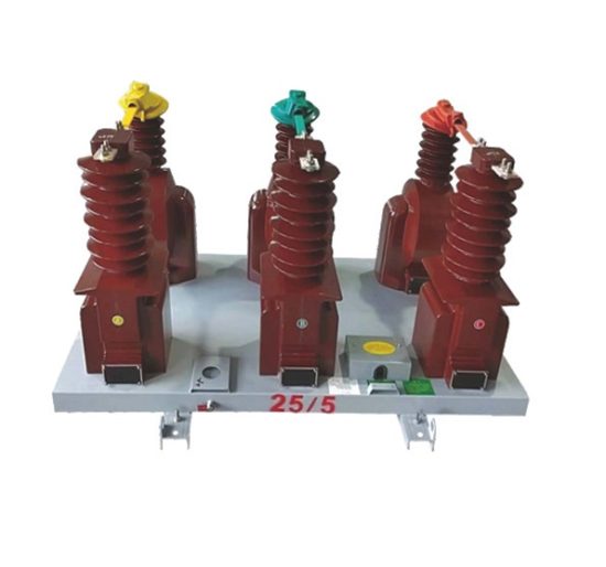
The LSZY-35 is a 33kV (IEC-rated) / 35kV (domestic system) outdoor-type cast-resin voltage transformer engineered for high-accuracy metering and reliable protection in medium-voltage power systems. Unlike legacy oil-immersed designs, the LSZY-35 employs vacuum pressure impregnated (VPI) epoxy resin insulation encapsulating a grain-oriented electrical steel (GOES) core, delivering superior dielectric strength, environmental resilience, and maintenance-free operation over its 25–30-year design life.
Operating Principle of Cast-Resin Insulation
Cast-resin insulation in the LSZY-35 utilizes a two-component cycloaliphatic epoxy resin system cured under vacuum and pressure to eliminate voids and moisture entrapment. This process ensures uniform dielectric distribution around primary and secondary windings, minimizing partial discharge activity to ≤5 pC at 1.2 × Um/√3 (where Um = 40.5 kV). The solid insulation provides mechanical rigidity, preventing winding displacement during short-circuit transients, while offering excellent tracking resistance (CTI ≥ 600 V per IEC 60112). Unlike oil-filled units, there is no risk of leakage, fire hazard, or environmental contamination—critical for urban substations and ecologically sensitive zones.
Advantages Over Oil-Immersed Designs
The LSZY-35 eliminates the operational liabilities inherent in oil-immersed VTs. With no liquid dielectric, it requires zero oil sampling, degassing, or level monitoring. Its compact footprint (typically 30% smaller than equivalent oil units) reduces structural loading on support insulators. Thermal stability is enhanced by the resin’s high thermal conductivity (0.8–1.2 W/m·K), enabling continuous operation at ambient temperatures from –40°C to +45°C without derating. Additionally, the absence of flammable oil allows installation in confined spaces or near combustible materials, complying with IEC 61869-3 Clause 7.3 for non-flammability. Maintenance intervals extend beyond five years versus annual checks for oil types, significantly lowering lifecycle costs.
Typical Application Overview
Deployed primarily in 35kV distribution networks, the LSZY-35 serves dual roles: supplying standardized secondary voltages (100 V or 100/√3 V) to revenue-class energy meters and providing scaled-down signals to protective relays (e.g., overvoltage, undervoltage, directional elements). It is commonly mounted on pole-top platforms, pad-mounted switchgear, or outdoor substation structures. Its robust UV-resistant housing withstands coastal salt fog, industrial pollution (Class III per IEC 60815), and seismic zones up to 0.3g. Applications span utility distribution feeders, industrial plant switchyards, solar farm collector substations, and railway traction networks where reliability and accuracy class 0.2/3P are mandated.
Technical Specifications
The LSZY-35 adheres strictly to IEC 61869-3 and GB/T 20840.3, with key parameters validated through type and routine tests at accredited laboratories.
| Parameter | Value |
|---|---|
| Primary Voltage (Up) | 33 kV (IEC) / 35 kV (GB) |
| Secondary Voltage(s) | 100 V (metering), 100/√3 V (protection) |
| Voltage Ratio | 33,000/100 V or 33,000/100/√3 V |
| Accuracy Class | 0.2 (metering), 3P (protection) |
| Rated Output (per burden) | 30 VA (0.2 class), 50 VA (3P class) |
| Insulation Level (LI/AC) | 170 kV / 70 kV |
| Short-Time Withstand Voltage | 70 kV rms, 1 min |
| Partial Discharge | ≤5 pC at 1.2 × 40.5/√3 kV |
| Core Material | GOES (Grain-Oriented Electrical Steel), M6 grade |
| Insulation System | VPI Epoxy Resin, UL 94 V-0 rated |
| Ambient Temperature Range | –40°C to +45°C |
| Altitude Limit | ≤1,000 m (derating required above) |
| Pollution Severity | Medium (Creepage distance: 25 mm/kV) |
Standard Service Conditions
The LSZY-35 is rated for standard service conditions per IEC 61869-3: ambient temperature between –40°C and +45°C, relative humidity up to 100% (condensation permitted), and installation altitude not exceeding 1,000 meters above sea level. At altitudes above 1,000 m, the dielectric withstand voltage must be reduced by 1% per 100 m increment. The transformer is designed for continuous operation under daily load cycles with harmonic distortion ≤5% THD. In coastal or industrial environments (pollution degree III), the creepage distance of 25 mm/kV ensures flashover resistance even under wet, contaminated conditions. Wind loading up to 35 m/s and seismic acceleration of 0.3g (horizontal and vertical) are accommodated without performance degradation.
Electrical Performance Parameters
Voltage error at rated frequency (50 Hz) and burden must remain within ±0.2% for class 0.2 and ±3% for class 3P. Phase displacement is limited to ±10 minutes for 0.2 class and ±120 minutes for 3P. The magnetizing current at 1.9 × Un (62.7 kV) shall not exceed 0.3 A to prevent ferroresonance in isolated neutral systems. Thermal stability is verified by temperature rise tests: winding rise ≤55 K above ambient when loaded at 1.2 × rated output continuously. Burden compatibility includes inductive, resistive, and mixed loads within specified VA ratings; exceeding burden causes accuracy drift and potential overheating.
Typical Applications
The LSZY-35 is engineered for diverse medium-voltage infrastructure requiring precision and durability.
Substation Secondary Metering
In 35kV utility substations, the LSZY-35 supplies 100 V secondary signals to Class 0.2S revenue meters for accurate kWh billing. Its low phase displacement (<10 arcmin) ensures minimal reactive energy measurement error. Installed on bus supports or circuit breakers, it interfaces with AMI (Advanced Metering Infrastructure) via communication-enabled metering cabinets. For three-phase systems, three single-pole LSZY-35 units are connected in star configuration with grounded neutral, enabling line-to-neutral and line-to-line voltage monitoring. Compliance with IEC 62053-22 guarantees traceable calibration for regulatory audits.
Industrial Power Distribution
Large manufacturing facilities (e.g., steel mills, chemical plants) deploy LSZY-35 units on 35kV switchgear to feed protection relays such as SEL-351 or Siemens 7SJ62. The 3P accuracy class ensures reliable operation during voltage sags or swells caused by motor startups or arc furnaces. The cast-resin design resists chemical vapors and dust ingress (IP54 rating), eliminating oil degradation risks. In arc-flash mitigation schemes, the VT provides synchronized voltage data for differential protection across multiple feeders, reducing fault clearance time to <100 ms.
Renewable Energy Integration
Solar and wind farms use LSZY-35 transformers at collector substation step-up points (35kV to 110kV/220kV). During grid faults, the VT maintains signal integrity for anti-islanding relays and low-voltage ride-through (LVRT) compliance per GB/T 19964. Its fast transient response (<20 ms settling time) captures voltage dips critical for grid-code certification. The non-flammable resin meets fire safety codes for containerized substations common in remote renewable sites.
Rural and Suburban Distribution Networks
In rural electrification projects, LSZY-35 units are pole-mounted on 35kV overhead lines feeding distribution transformers. Their lightweight design (≈85 kg) simplifies helicopter or truck crane installation in mountainous terrain. The wide operating temperature range ensures accuracy in desert (≥45°C) or alpine (≤–30°C) climates. For smart grid rollouts, secondary terminals connect to RTUs for SCADA voltage profiling, enabling dynamic VAR compensation.
Compliance with International Standards
The LSZY-35 is certified to both global and Chinese national standards, ensuring interoperability and regulatory acceptance.
IEC 61869-3 Certification Details
IEC 61869-3 governs electromagnetic voltage transformers for measurement and protection. The LSZY-35 meets all clauses, including insulation coordination (Clause 6), accuracy requirements (Clause 7), and thermal behavior (Clause 8). Type tests include power-frequency withstand (70 kV, 1 min), lightning impulse (170 kV peak, 1.2/50 μs waveform), and temperature rise (≤55 K). Routine tests—ratio verification (±0.1% tolerance), polarity check, and partial discharge—are performed on 100% of units. The certificate includes test reports from SGS or TÜV confirming compliance with Edition 2.0 (2011).
Alignment with GB/T 20840.3
GB/T 20840.3 mirrors IEC 61869-3 but specifies 35kV as nominal system voltage (vs. IEC’s 33kV). The LSZY-35 is dual-rated: primary winding designed for 35kV RMS continuous operation while meeting IEC’s 33kV test protocols. Key GB-specific requirements include higher creepage distance (25 mm/kV vs. IEC’s 20 mm/kV for medium pollution) and mandatory seismic testing per GB/T 13540. All units undergo China CQC certification, with factory serial numbers traceable to national quality databases.
Differences Between IEC and Domestic Standards
While IEC 61869-3 uses 33kV as the reference voltage for 35kV-class systems (based on Um = 40.5 kV), GB/T 20840.3 directly references 35kV. This affects ratio labeling but not physical design—the LSZY-35’s turns ratio is calculated for 35,000 V primary. GB standards also mandate stricter short-circuit withstand verification (3-second duration vs. IEC’s 1-second) and require flame-retardant resin tested per GB/T 5169.16. Despite these nuances, the LSZY-35 achieves full harmonization, allowing export to IEC markets and domestic deployment without modification.
On-Site Testing Procedures
Post-installation commissioning ensures the LSZY-35 performs within specification before energization.
Insulation Resistance Test
Using a 2,500 V DC megohmmeter, measure insulation resistance between primary winding and ground, and between secondary windings and ground. Acceptance criterion: ≥10,000 MΩ at 20°C. Correct for temperature using RT = R20 × 2(20–T)/10. Values below 1,000 MΩ indicate moisture ingress or resin cracking, requiring drying or replacement. Perform before and after power-frequency withstand tests to detect insulation degradation.
Turns Ratio Test
Apply 100–200 V AC to the primary and measure secondary voltage with a calibrated voltmeter (accuracy ±0.1%). Calculate actual ratio: Vp/Vs. Tolerance must be within ±0.1% of nameplate ratio (e.g., 330 ±0.33 for 33,000/100 V). Use a dedicated ratio tester (e.g., Omicron CT Analyzer) for automated comparison. Deviations >0.2% suggest winding shorts or incorrect tap selection.
Polarity Test
Verify reducing polarity per IEC 61869-3 Figure 3. Connect a 6–12 V battery across primary terminals (H1+, H2–). Momentarily close the circuit while monitoring secondary with a DC millivoltmeter (X1+, X2–). A positive kick confirms correct polarity. Incorrect polarity reverses relay operation—critical for directional overcurrent schemes. Repeat three times to eliminate contact bounce artifacts.
Power Frequency Withstand Voltage Test
Apply 70 kV RMS at 50 Hz between primary and grounded secondary/core for 1 minute. Use a calibrated test transformer with overcurrent trip (≤100 mA). No flashover or disruptive discharge is permitted. Gradually ramp voltage (≤1 kV/s) to avoid transient overstress. Post-test, recheck insulation resistance; a drop >20% indicates latent damage.
Open-Circuit Characteristic Test
With secondary open, apply 0–120% of rated primary voltage (0–39.6 kV) in 10% increments. Record excitation current. At 100% voltage, current should be ≤0.1 A; at 120%, ≤0.25 A. Plot V vs. I curve—nonlinearity beyond knee point (>110%) indicates core saturation risk. Excessive magnetizing current (>0.3 A at 120%) may trigger ferroresonance in ungrounded systems.
Preventive Maintenance Guide
Although cast-resin VTs are largely maintenance-free, periodic checks ensure longevity.
Annual Visual and Functional Inspection
Inspect housing for cracks, UV degradation, or tracking marks. Clean sheds with deionized water if pollution layer exceeds 0.1 mm thickness. Check terminal tightness (torque: 15 N·m for M10 bolts) and grounding continuity (<0.1 Ω resistance). Verify secondary wiring for loose connections or insulation wear. Perform ratio and polarity spot-checks if system disturbances occurred (e.g., nearby faults).
Five-Year Comprehensive Maintenance
Every 60 months, conduct insulation resistance, partial discharge (using portable PD detector), and open-circuit tests. Partial discharge >10 pC warrants internal inspection via endoscopy. Review historical data trends—rising excitation current or falling insulation resistance indicates aging. Replace silica gel in terminal box desiccant (if equipped). Update asset management records with test results for predictive analytics.
Maintenance Intervals and Fault Diagnosis
| Interval | Action | Fault Indicator |
|---|---|---|
| Annually | Visual, torque, IR test | Cracks, loose terminals, IR <1,000 MΩ |
| 5 Years | PD, ratio, OC test | PD >10 pC, ratio error >0.2% |
| After Fault | Full commissioning suite | Relay misoperation, blown fuses |
Common failures include secondary winding open-circuit (causing infinite burden and core saturation) or terminal corrosion leading to measurement drift. Never operate with secondary open—always short-circuit during disconnection to prevent dangerous overvoltages.
Conclusion
The LSZY-35 33kV cast-resin voltage transformer represents a technically mature solution for outdoor metering and protection in 35kV-class power systems. By leveraging VPI epoxy resin insulation and GOES cores, it achieves IEC 61869-3 and GB/T 20840.3 compliance with inherent advantages over oil-immersed alternatives: zero fire risk, minimal maintenance, and superior environmental resilience. Its dual accuracy classes (0.2 for revenue metering, 3P for protection) ensure precise energy billing and dependable relay coordination across diverse applications—from urban substations to remote renewable sites. Rigorous factory and field testing protocols guarantee performance within tight tolerances (±0.1% ratio error, ≤5 pC partial discharge), while a design life of 25–30 years delivers exceptional lifecycle value. For engineers specifying instrument transformers in medium-voltage networks, the LSZY-35 offers a future-proof, standards-compliant choice that balances precision, safety, and operational economy.