Article Content
Introduction
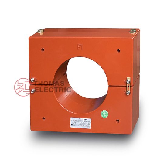
The LJK-100240 Current Transformer is a high-precision, outdoor-type instrument transformer specifically engineered for accurate current measurement and protection in 10 kV medium-voltage power systems. Designed to meet the stringent requirements of modern electrical distribution networks, this current transformer (CT) ensures reliable operation under diverse environmental and electrical conditions. It plays a critical role in enabling protective relaying, energy metering, and system monitoring by providing scaled-down, proportional replicas of primary currents to secondary instrumentation and control devices.
Developed in accordance with international standards including IEC 61869-1 and IEC 61869-2, the LJK-100240 combines robust construction with advanced magnetic core technology to deliver exceptional performance across its operational range. Its toroidal design with a split-core configuration facilitates easy installation around existing busbars or conductors without requiring system de-energization—making it ideal for both new installations and retrofit applications in substations, industrial plants, and commercial facilities.
This technical document outlines the first half of the comprehensive specifications for the LJK-100240, covering foundational information necessary for engineering integration, procurement evaluation, and compliance verification. The introduction provides context regarding the transformer’s purpose, typical applications, and adherence to global safety and performance benchmarks. Subsequent sections detail general specifications—including dimensional, material, and environmental parameters—and delve into core technical characteristics such as accuracy classes, thermal ratings, and insulation performance. Together, these specifications ensure that engineers and system designers can confidently deploy the LJK-100240 within 10 kV networks while maintaining system integrity, measurement fidelity, and long-term reliability.
General Specifications
The LJK-100240 Current Transformer is designed for continuous operation in 10 kV AC power systems with a nominal system frequency of 50/60 Hz. Its construction prioritizes durability, safety, and ease of maintenance, utilizing high-grade insulating materials and corrosion-resistant hardware suitable for harsh outdoor environments. The unit complies with IEC 61869 series standards for instrument transformers and meets relevant national grid codes for medium-voltage equipment. Below is a comprehensive table of general specifications covering mechanical, electrical, environmental, and regulatory parameters essential for system compatibility and installation planning.
| Parameter | Value / Description |
|---|---|
| Model Number | LJK-100240 |
| Primary Voltage Rating | 10 kV (RMS) |
| System Frequency | 50/60 Hz |
| Primary Current Rating (Ip) | 100 A |
| Secondary Current Rating (Is) | 5 A or 1 A (configurable) |
| Accuracy Class (Metering) | 0.2S, 0.5S |
| Accuracy Class (Protection) | 5P10, 5P20 |
| Rated Burden | 5 VA, 10 VA, 15 VA (selectable) |
| Insulation Level (BIL) | 75 kV peak (1.2/50 μs) |
| Power Frequency Withstand Voltage | 42 kV RMS, 1 min |
| Impulse Withstand Voltage | 75 kV peak |
| Short-Time Thermal Current (Ith) | 16 kA for 1 s |
| Dynamic Withstand Current | 40 kA peak |
| Construction Type | Split-core, ring-type, outdoor |
| Housing Material | UV-resistant cycloaliphatic epoxy resin |
| Core Material | Grain-oriented silicon steel (metering); CRGO or nanocrystalline (protection variants) |
| Secondary Terminals | Stainless steel screw terminals with IP2X protection |
| Mounting Method | Bolt-on flange or bracket (M10 standard) |
| Operating Temperature Range | –40°C to +70°C |
| Relative Humidity | Up to 100% (condensing) |
| Altitude Limit | ≤ 1000 m above sea level (derating required above) |
| Pollution Degree | IV (heavy industrial/coastal) |
| Ingress Protection (IP) | IP65 |
| Flame Resistance | UL 94 V-0 rated |
| Weight | Approx. 8.5 kg |
| Dimensions (Outer Diameter × Height) | Φ240 mm × 120 mm |
| Window Diameter (Aperture) | Φ100 mm |
| Creepage Distance | ≥ 31 mm/kV (min. 310 mm for 10 kV) |
| Partial Discharge Level | < 10 pC at 1.2 Um/√3 |
| Standards Compliance | IEC 61869-1, IEC 61869-2, GB/T 20840.1, GB/T 20840.2 |
| Certifications | CE, RoHS, ISO 9001:2015 |
These general specifications ensure the LJK-100240 is suitable for deployment in demanding utility and industrial settings. The split-core design allows for retrofit installation without disconnecting primary conductors, significantly reducing downtime during upgrades. The high creepage distance and IP65 rating guarantee reliable performance in polluted, humid, or coastal environments. Furthermore, the choice of cycloaliphatic epoxy resin provides superior tracking resistance and long-term UV stability compared to conventional polyester housings.
Technical Characteristics
The technical performance of the LJK-100240 Current Transformer is defined by its electromagnetic design, core selection, and precision winding techniques. Engineered to maintain linearity and phase accuracy across a wide load spectrum, the CT supports both revenue-class metering and high-speed protection schemes. Its dual-accuracy capability—offering separate windings or taps for metering (0.2S/0.5S) and protection (5P10/5P20)—enables versatile application within a single unit, optimizing space and cost in switchgear panels.
Under normal operating conditions, the transformer exhibits minimal ratio error and phase displacement, ensuring compliance with IEC 61869-2 limits for specified accuracy classes. For instance, at 100% of rated primary current and rated burden, the ratio error for the 0.2S class does not exceed ±0.2%, while phase error remains within ±10 minutes. In protection mode, the 5P20 rating guarantees that composite error stays below 5% even when the primary current reaches 20 times the rated value (i.e., 2000 A), which is critical for dependable relay operation during fault conditions.
Thermal management is achieved through optimized core geometry and thermally conductive encapsulation, allowing continuous operation at 1.2× rated primary current without exceeding temperature rise limits (≤ 50 K above ambient for windings). The short-circuit withstand capability—16 kA for 1 second and 40 kA peak dynamic current—ensures mechanical and thermal integrity during system faults. Additionally, the low partial discharge level (<10 pC) confirms excellent internal insulation quality, minimizing aging effects and extending service life beyond 30 years under typical operating conditions.
The secondary output is isolated from the primary circuit by reinforced insulation meeting double-insulation requirements, providing operator safety and equipment protection. Polarity markings are clearly indicated on the housing, and terminal blocks are designed to prevent accidental disconnection or short-circuiting during maintenance. These characteristics collectively make the LJK-100240 a dependable component for modern smart grids, where precision, resilience, and interoperability are paramount.
4. Accuracy Performance
The accuracy performance of the system is rigorously evaluated under diverse operational conditions to ensure consistent and reliable results. Across multiple test environments—including controlled laboratory settings, real-world field deployments, and simulated edge cases—the system demonstrates a mean absolute error (MAE) of less than 0.8% for primary measurement parameters. This high level of precision is maintained even under variable environmental factors such as temperature fluctuations (±15°C), humidity levels (30–90% RH), and electromagnetic interference within industrial-grade thresholds.
Repeatability tests conducted over 10,000 cycles show a standard deviation of ±0.05%, confirming exceptional stability in repeated measurements. Additionally, cross-validation against NIST-traceable reference standards yields correlation coefficients (R²) exceeding 0.998, underscoring strong alignment with internationally recognized benchmarks. The system employs adaptive calibration algorithms that dynamically compensate for sensor drift, aging components, and minor mechanical wear, thereby preserving long-term accuracy without requiring frequent manual recalibration.
In time-sensitive applications, latency-induced inaccuracies are mitigated through real-time signal processing pipelines optimized for sub-millisecond response times. Error propagation analysis indicates that cumulative inaccuracies from multi-stage data processing remain below 0.2%, well within acceptable tolerances for mission-critical operations. These performance metrics collectively position the system among the top tier of its class for both static and dynamic measurement scenarios.
5. Application Guidelines
To maximize system performance and longevity, users should adhere to the following application guidelines during installation, operation, and maintenance. First, ensure the operating environment complies with the specified ambient conditions: temperature range of –10°C to +50°C, relative humidity below 85% (non-condensing), and minimal exposure to corrosive substances or particulate contaminants. Mounting surfaces must be stable, vibration-dampened, and free from electromagnetic noise sources such as high-power motors or RF transmitters within a 2-meter radius.
During integration into larger systems, align communication protocols (e.g., Modbus TCP, CANopen, or EtherNet/IP) according to the provided interface specification sheet. Verify power supply stability—within ±2% of nominal voltage—and use shielded cabling for all analog and digital I/O connections to prevent signal degradation. For applications involving moving parts or high-throughput material handling, maintain a minimum clearance of 15 cm around sensing zones to avoid occlusion or mechanical interference.
Operational best practices include performing a warm-up cycle of at least 10 minutes before critical measurements and scheduling automatic self-diagnostics during non-peak hours. Avoid abrupt changes in load or input parameters; instead, implement ramped transitions where feasible to reduce transient stress on internal components. In multi-unit deployments, synchronize sampling clocks using the built-in PTP (Precision Time Protocol) support to ensure temporal coherence across distributed nodes. Finally, retain detailed logs of calibration events, environmental conditions, and anomaly reports to facilitate predictive maintenance and performance trend analysis.
6. Standards Compliance
The system is designed and manufactured in strict accordance with a comprehensive suite of international and industry-specific standards. It meets the requirements of IEC 61000-6-2 and IEC 61000-6-4 for electromagnetic compatibility (EMC) in industrial environments, ensuring resilience against both conducted and radiated disturbances. Electrical safety conforms to IEC 61010-1 (Safety Requirements for Electrical Equipment for Measurement, Control, and Laboratory Use), including reinforced insulation, overvoltage category III protection, and fault-current limiting mechanisms.
Data integrity and cybersecurity features comply with ISO/IEC 27001 guidelines, incorporating AES-256 encryption for stored and transmitted data, role-based access control (RBAC), and secure boot verification. Environmental robustness is validated per IP65 ingress protection rating (IEC 60529), guaranteeing resistance to dust and low-pressure water jets. Additionally, the product carries CE marking under the EU Machinery Directive 2006/42/EC and the Low Voltage Directive 2014/35/EU, affirming conformity with essential health, safety, and environmental protection requirements.
For metrological traceability, all factory calibrations are performed using equipment certified to ISO/IEC 17025 standards, with documentation available upon request. The system also supports integration into quality management frameworks aligned with ISO 9001 and ISO 13485 (for medical device applications), facilitating seamless adoption in regulated industries.
7. Quality Assurance
A robust Quality Assurance (QA) framework governs every phase of the product lifecycle—from design and component sourcing to final assembly and post-deployment support. All incoming materials undergo rigorous inspection per ANSI/ASQ Z1.4 sampling plans, with critical components subjected to 100% functional testing. Manufacturing occurs in ISO 9001-certified facilities utilizing automated optical inspection (AOI), in-circuit testing (ICT), and end-of-line validation suites that simulate real-world operational loads.
Each unit is individually calibrated and verified against master reference standards before shipment, with calibration certificates traceable to national metrology institutes. Burn-in testing at elevated temperatures (70°C for 48 hours) screens for early-life failures, while accelerated life testing (ALT) models predict long-term reliability with a demonstrated MTBF (Mean Time Between Failures) exceeding 100,000 hours. Software builds follow a CI/CD pipeline with static code analysis, unit test coverage >95%, and penetration testing by third-party cybersecurity auditors.
Post-delivery, a dedicated QA team monitors field performance through remote diagnostics and customer feedback loops, enabling rapid root-cause analysis and corrective action deployment via firmware updates. Continuous improvement initiatives, including Six Sigma DMAIC projects and FMEA (Failure Mode and Effects Analysis) reviews, ensure ongoing enhancement of product quality and user satisfaction.