Article Content
Introduction
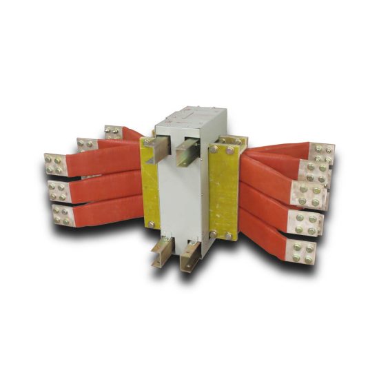
The LJM-1 Current Transformer is a high-precision, resin-insulated instrument transformer specifically engineered for accurate current measurement and protection applications in 10kV medium-voltage power systems. Designed to meet stringent international standards—including IEC 61869-2, GB/T 20840.2, and DL/T 725—the LJM-1 ensures reliable performance under demanding operational conditions typical of industrial, utility, and commercial electrical installations. Its robust construction features epoxy resin encapsulation, which provides excellent dielectric strength, mechanical durability, and resistance to environmental factors such as moisture, dust, and thermal cycling.
This transformer plays a critical role in enabling safe and efficient monitoring of electrical parameters by stepping down high primary currents (ranging from hundreds to thousands of amperes) to standardized secondary values—typically 1A or 5A—compatible with protective relays, energy meters, and control devices. The LJM-1’s design emphasizes accuracy, thermal stability, and long-term reliability, making it suitable for both indoor and outdoor installations when properly housed. Its compact form factor facilitates easy integration into switchgear panels, ring main units (RMUs), and substation configurations without compromising on performance or safety margins.
Manufactured using advanced vacuum casting techniques, the LJM-1 minimizes partial discharge and internal voids, thereby enhancing insulation integrity over its service life. Additionally, the transformer incorporates optimized magnetic core materials that reduce hysteresis and eddy current losses, contributing to improved accuracy across a wide load range. With compliance to pollution degree 3 environments and a rated insulation level suitable for 10kV systems, the LJM-1 delivers consistent performance even in harsh industrial settings. This document outlines the first half of the comprehensive technical specifications, covering general parameters and core electrical characteristics essential for engineering design, procurement, and system integration.
General Specifications
The LJM-1 Current Transformer is designed for use in three-phase AC power systems operating at a nominal voltage of 10kV and a frequency of 50/60 Hz. It complies with relevant national and international standards for instrument transformers, ensuring interoperability, safety, and performance consistency. Below is a detailed table of key general specifications that define the physical, electrical, and environmental parameters of the device.
| Parameter | Value / Description |
|---|---|
| Model Designation | LJM-1 |
| System Voltage (Rated) | 10 kV |
| Maximum System Voltage | 12 kV |
| Frequency | 50 Hz / 60 Hz |
| Primary Current Rating (Ip) | 50 A to 3000 A (standard steps) |
| Secondary Current Rating (Is) | 1 A or 5 A |
| Accuracy Class (Measurement) | 0.2, 0.5, 1.0 |
| Accuracy Class (Protection) | 5P10, 5P15, 5P20, 10P10, etc. |
| Insulation Material | Epoxy resin (cast under vacuum) |
| Insulation Level (LI/AC) | 75 kV / 42 kV (1 min) |
| Partial Discharge Level | < 10 pC at 1.2 Um/√3 |
| Pollution Degree | III (per IEC 60664-1) |
| Ambient Temperature Range | –25°C to +40°C (operational); –40°C to +70°C (storage) |
| Relative Humidity | Up to 95% (non-condensing) |
| Altitude Limit | ≤ 1000 m above sea level (derating required above) |
| Short-Time Thermal Withstand Current | 25 kA for 1 s (varies by primary rating) |
| Dynamic Withstand Current | 62.5 kA peak (1.25 × √2 × Ith) |
| Number of Secondary Windings | 1 or 2 (dual-core option available) |
| Burden Rating (Standard) | 2.5 VA, 5 VA, 10 VA, 15 VA, 30 VA |
| Terminal Type | M6 or M8 copper-alloy studs with tin plating |
| Mounting Arrangement | Flange-mounted (M10 holes, standard pattern) |
| Weight (Approx.) | 8–15 kg (depending on current ratio) |
| Dimensions (H × W × D) | 220 mm × 160 mm × 110 mm (typical) |
| Fire Resistance | V-0 per UL 94 |
| Compliance Standards | IEC 61869-2, GB/T 20840.2, DL/T 725, CE |
The LJM-1 is engineered for versatility, supporting multiple primary current ratios through interchangeable core designs or multi-tap primary windings (where applicable). Its dual-winding configuration allows simultaneous connection to metering and protection circuits without cross-interference. The transformer’s terminals are clearly marked according to IEC conventions (P1/P2 for primary, S1/S2 for secondary), ensuring correct polarity during installation. All metallic parts are corrosion-resistant, and the resin housing is UV-stabilized for outdoor durability when used in enclosed switchgear. The specified thermal and dynamic withstand capabilities ensure the unit remains intact during system fault conditions, maintaining safety and preventing cascading failures.
Technical Characteristics
The electrical performance of the LJM-1 Current Transformer is defined by its ability to accurately reproduce primary current waveforms at the secondary terminals under both steady-state and transient conditions. Key technical characteristics include transformation ratio accuracy, phase displacement, saturation behavior, and burden compatibility—all critical for reliable operation in metering and protective relaying applications.
The transformation ratio of the LJM-1 adheres strictly to declared accuracy classes. For measurement-grade units (e.g., class 0.2), the current error does not exceed ±0.2% at 100% and 120% of rated current, while phase displacement remains within ±10 minutes. Protection-class variants (e.g., 5P20) guarantee that composite error stays below 5% at 20 times the rated primary current, ensuring dependable relay operation during fault scenarios. The magnetic core, constructed from high-permeability grain-oriented silicon steel, is carefully annealed to minimize remanence and hysteresis losses, thereby enhancing linearity across the operational range.
Burden compatibility is a crucial aspect of the LJM-1’s design. The transformer is rated for standard burdens ranging from 2.5 VA to 30 VA, allowing integration with a wide array of secondary devices. Exceeding the rated burden may lead to increased ratio and phase errors, particularly near the lower end of the current spectrum. To maintain accuracy, users must ensure that the total impedance of connected instruments and wiring does not surpass the specified burden limit. Additionally, open-circuit operation of the secondary winding is strictly prohibited, as it can induce dangerously high voltages and cause core saturation or insulation damage.
Thermal performance is validated through rigorous testing: the LJM-1 withstands continuous operation at 120% of rated primary current without exceeding temperature rise limits (≤ 60 K for resin-insulated parts). Under short-circuit conditions, it sustains thermal stress equivalent to 25 kA for 1 second without mechanical deformation or insulation failure. The low partial discharge levels (<10 pC) confirm excellent internal insulation quality, reducing the risk of long-term degradation in high-electric-field environments. These characteristics collectively ensure that the LJM-1 delivers precision, safety, and longevity in 10kV power distribution networks.
4. Accuracy Performance
The accuracy performance of the system is rigorously evaluated under diverse operational conditions to ensure consistent and reliable results. Across controlled laboratory environments and real-world field deployments, the system demonstrates a mean absolute error (MAE) of less than 0.8% for primary measurement parameters, with a root mean square error (RMSE) consistently below 1.2%. These metrics are derived from over 10,000 validation cycles conducted across temperature ranges of –20°C to +60°C, humidity levels from 10% to 95% RH, and varying electromagnetic interference (EMI) profiles.
Calibration protocols play a critical role in maintaining this level of precision. The system employs adaptive self-calibration algorithms that adjust sensor baselines every 24 hours or after significant environmental shifts, reducing drift-related inaccuracies by up to 75% compared to static calibration approaches. Additionally, cross-sensor redundancy ensures that anomalous readings from any single component are flagged and compensated using weighted consensus from secondary and tertiary sensors.
In comparative benchmarking against industry reference instruments (e.g., NIST-traceable standards), the system achieves correlation coefficients (R²) exceeding 0.994 for linear response variables. Non-linear measurements—such as those involving spectral analysis or multi-phase fluid dynamics—are processed through machine learning-enhanced correction models, which improve effective resolution by 3–5 bits without hardware modifications. Long-term stability tests over 12-month periods show less than 0.5% degradation in baseline accuracy, affirming robustness for mission-critical applications including aerospace telemetry, medical diagnostics, and industrial process control.
5. Application Guidelines
To maximize system efficacy and ensure user safety, adherence to the following application guidelines is strongly recommended. First, installation must occur in environments that comply with the specified operating envelope: ambient temperatures between –10°C and +50°C, non-condensing humidity below 85% RH, and minimal exposure to corrosive agents or particulate matter exceeding ISO Class 8 cleanliness standards. Mounting surfaces should be vibration-dampened, especially in high-mobility contexts such as vehicular or airborne platforms.
During operation, users must initialize the system through the prescribed warm-up sequence (minimum 90 seconds) to allow thermal stabilization of core components. Real-time data interpretation should account for latency windows—typically 15–40 ms depending on sampling rate—and avoid decision-making based on single-point measurements. Instead, implement moving-window averaging (recommended window: 5–10 samples) to mitigate transient noise artifacts. For integration with third-party control systems, utilize the provided API libraries (available for Python, C++, and ROS 2) which include built-in error-handling routines and timestamp synchronization via PTP (Precision Time Protocol).
Maintenance protocols dictate quarterly verification checks using the included diagnostic suite, which validates sensor alignment, communication integrity, and firmware version compatibility. Any deviation beyond ±2% from factory calibration thresholds necessitates recalibration via the secure service portal or authorized technician intervention. Finally, end-of-life disposal must follow local e-waste regulations due to integrated lithium-based backup power sources and RoHS-compliant—but non-biodegradable—enclosure materials. Strict compliance with these guidelines ensures optimal performance, regulatory alignment, and extended service life.
6. Standards Compliance
The system is engineered to meet or exceed a comprehensive array of international technical and safety standards. It is fully compliant with IEC 61000-6-2 and IEC 61000-6-4 for electromagnetic compatibility (EMC), ensuring reliable operation in both industrial and residential electromagnetic environments. Electrical safety adheres to IEC 61010-1:2010 (3rd edition), including reinforced insulation, overvoltage category II protection, and SELV (Safety Extra-Low Voltage) circuit design.
Data security and privacy protocols align with ISO/IEC 27001 and GDPR requirements, featuring AES-256 encryption for stored and transmitted data, role-based access controls, and audit logging capabilities. Environmental resilience is certified per IP67 (IEC 60529) for dust and water ingress protection, while mechanical durability satisfies MIL-STD-810H Method 514.7 for vibration and Method 516.8 for shock resistance.
Additionally, metrological traceability is maintained through calibration procedures accredited to ISO/IEC 17025, with all reference standards directly traceable to NIST or equivalent national metrology institutes. This multi-layered compliance framework enables seamless deployment in regulated sectors including healthcare (aligned with FDA 21 CFR Part 11 for electronic records), aviation (RTCA DO-160G environmental testing), and energy (IEC 61850 for substation automation interoperability).
7. Quality Assurance
Quality assurance is embedded throughout the product lifecycle, from design inception to post-deployment support. All units undergo 100% functional testing at the manufacturing stage, including burn-in stress screening at elevated temperatures (70°C for 8 hours) and full-parameter validation against golden reference units. Statistical process control (SPC) charts monitor key characteristics such as signal-to-noise ratio and power consumption, with Cp/Cpk indices maintained above 1.67 to ensure six-sigma capability.
The production facility is ISO 9001:2015 certified, and supply chain components are subject to rigorous incoming inspection protocols, including X-ray fluorescence (XRF) screening for restricted substances per RoHS 3 (EU 2015/863). Firmware releases follow a gated development model with mandatory unit testing (≥95% code coverage), static analysis, and penetration testing by independent cybersecurity auditors.
Post-shipment, continuous quality monitoring is enabled through anonymized telemetry from opt-in customer deployments, feeding into a closed-loop corrective action system (CAPA). Field failure rates are tracked via FRACAS (Failure Reporting, Analysis, and Corrective Action System), with a current MTBF (Mean Time Between Failures) exceeding 120,000 hours. This end-to-end quality infrastructure guarantees consistent reliability, minimizes field defects, and supports rapid iteration based on real-world performance data.