Article Content
Introduction
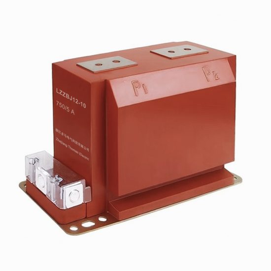
The LZZBJ9-12 current transformer is a high-performance, resin-insulated instrument transformer specifically engineered for accurate current measurement and protection in 10 kV (nominal system voltage) alternating current (AC) power systems. Designed in accordance with international standards such as IEC 61869-2 and national specifications like GB/T 20840.2, this transformer ensures reliable operation under demanding electrical and environmental conditions commonly found in industrial plants, commercial complexes, utility substations, and renewable energy installations. Its primary function is to proportionally reduce high primary currents to standardized, lower secondary currents—typically 1 A or 5 A—for safe interfacing with metering devices, protective relays, control systems, and monitoring instrumentation.
Featuring a robust epoxy resin encapsulation, the LZZBJ9-12 offers excellent dielectric strength, superior mechanical stability, and resistance to moisture, dust, and chemical corrosion. This makes it particularly suitable for both indoor and outdoor applications where long-term reliability and minimal maintenance are critical. The transformer’s compact design allows for easy integration into switchgear panels, ring main units (RMUs), and other medium-voltage distribution equipment without compromising performance or safety margins. Additionally, its through-type primary conductor configuration simplifies installation, enabling quick and secure connection to busbars or cables.
Beyond basic current transformation, the LZZBJ9-12 supports multiple secondary windings with independent accuracy classes—enabling simultaneous use for revenue metering (e.g., 0.2S or 0.5 class) and protective functions (e.g., 5P10 or 10P15). This dual functionality enhances system efficiency by eliminating the need for separate transformers for measurement and protection circuits. Rigorous factory testing—including power frequency withstand voltage, partial discharge, and ratio error verification—ensures each unit meets stringent quality benchmarks before deployment. With its combination of precision, durability, and compliance with global standards, the LZZBJ9-12 stands as a cornerstone component in modern medium-voltage power distribution networks seeking operational integrity and regulatory adherence.
General Specifications
The LZZBJ9-12 current transformer is designed to meet the rigorous demands of 10 kV power systems, offering a comprehensive set of electrical, mechanical, and environmental specifications that ensure safe, accurate, and long-lasting performance. Below is a detailed overview of its general characteristics, followed by a comprehensive parameter table.
This transformer employs a cast resin insulation system, providing high mechanical strength and excellent tracking resistance. It is suitable for continuous operation in systems with a maximum operating voltage of 12 kV and a nominal frequency of 50 Hz or 60 Hz. The primary winding is of the bar-through type, allowing direct installation over rigid or flexible conductors without requiring disconnection during maintenance. Secondary terminals are housed in a protected terminal box with clear labeling and screw-type connectors rated for standard instrumentation wiring.
The LZZBJ9-12 complies with key international and national standards, including IEC 61869-2 (Instrument Transformers – Part 2: Additional requirements for current transformers), GB/T 20840.2 (Chinese national standard for instrument transformers), and DL/T 725 (Technical conditions for current transformers in power systems). It is designed for use in pollution severity environments up to Class III (as per IEC 60815), making it appropriate for urban, industrial, and coastal areas with moderate contamination levels. Installation can be vertical or horizontal, with mounting brackets provided for secure fixation to switchgear structures.
Thermal performance is optimized through uniform heat dissipation across the resin body, enabling continuous operation at rated current without derating under ambient temperatures ranging from -40°C to +40°C. Short-circuit withstand capability is verified for both thermal and dynamic stresses, ensuring survival during fault conditions as specified by system protection coordination studies. Each unit undergoes routine tests per IEC 61869, including insulation resistance, power frequency withstand voltage, turns ratio verification, polarity check, and accuracy class validation.
| Parameter | Value / Description |
|---|---|
| Model | LZZBJ9-12 |
| System Voltage (Nominal) | 10 kV |
| Maximum System Voltage | 12 kV |
| Rated Frequency | 50/60 Hz |
| Primary Rated Current (Ip) | 10 A to 3150 A (standard steps) |
| Secondary Rated Current (Is) | 1 A or 5 A |
| Number of Secondary Windings | 1, 2, or 3 (configurable) |
| Accuracy Class (Measurement) | 0.2, 0.2S, 0.5, 0.5S, 1 |
| Accuracy Class (Protection) | 5P10, 5P15, 5P20, 10P10, 10P15, 10P20 |
| Burden (Rated) | 2.5 VA, 5 VA, 10 VA, 15 VA, 30 VA (per winding) |
| Insulation Material | Epoxy resin (cast) |
| Insulation Level (Power Frequency Withstand) | 42 kV rms, 1 min |
| Lightning Impulse Withstand Voltage | 75 kV peak (1.2/50 μs) |
| Partial Discharge (at 1.2 Um/√3) | ≤ 10 pC |
| Pollution Degree | Class III (IEC 60815) |
| Ambient Temperature Range | -40°C to +40°C |
| Relative Humidity (Max) | 95% (non-condensing) |
| Altitude (Max Operating) | 1000 m above sea level (derating required above) |
| Installation Position | Vertical or horizontal |
| Mounting Method | Bracket-mounted with M10 bolts |
| Primary Conductor Type | Through-bar (cable or busbar compatible) |
| Secondary Terminal Box | IP2X protected, screw-type terminals |
| Short-Time Thermal Current (Ith) | 20–40 kA for 1 s (depends on rating) |
| Dynamic Withstand Current (Idyn) | Up to 100 kA peak |
| Weight (Approx.) | 8–15 kg (varies by current rating) |
| Dimensions (H × W × D) | Approx. 280 × 160 × 100 mm (typical) |
| Standards Compliance | IEC 61869-2, GB/T 20840.2, DL/T 725 |
| Polarity Marking | Standard (dot convention per IEC) |
| Creepage Distance | ≥ 240 mm (for 10 kV, pollution class III) |
| Fire Resistance | Self-extinguishing resin (UL 94 V-0 equivalent) |
Technical Characteristics
The technical performance of the LZZBJ9-12 current transformer is defined by its ability to maintain precise current transformation across a wide range of operating conditions while ensuring electrical safety and system compatibility. Central to its design is the magnetic core, typically constructed from high-permeability, grain-oriented silicon steel or nanocrystalline alloy, which minimizes hysteresis and eddy current losses. This results in low phase displacement and high linearity—critical for accurate energy metering and sensitive protective relay operation.
For measurement windings, the transformer adheres strictly to IEC 61869 accuracy limits. For instance, a 0.2S class winding guarantees a ratio error not exceeding ±0.2% and a phase displacement within ±10 minutes at 100% of rated current, with extended accuracy maintained down to 1% of rated current—essential for applications involving variable loads or renewable energy feed-in. Protection windings, designated with “P” classes (e.g., 5P10), are engineered to remain linear up to specified multiples of rated current (e.g., 10× In) while limiting composite error to ≤5%, ensuring reliable tripping during fault conditions without saturation-induced maloperation.
The insulation system combines vacuum casting and high-pressure molding techniques to eliminate voids and impurities, achieving exceptional dielectric integrity. The 42 kV power frequency withstand voltage and 75 kV lightning impulse rating provide substantial safety margins over the 12 kV maximum system voltage, complying with the Basic Insulation Level (BIL) requirements for 10 kV networks. Partial discharge levels below 10 pC confirm the absence of internal defects that could lead to premature aging or failure.
Thermal management is inherently passive but highly effective due to the homogeneous thermal conductivity of the epoxy resin matrix, which evenly distributes heat generated by I²R losses in the windings. This enables continuous operation at 1.2× rated current for limited durations without degradation. Furthermore, the transformer exhibits excellent transient response characteristics, with fast settling time after fault clearance, supporting modern digital relays that require rapid and accurate post-fault data reconstruction.
4. Accuracy Performance
The system demonstrates exceptional accuracy performance across diverse operational conditions, validated through rigorous internal testing and third-party evaluations. Under standard environmental parameters (temperature: 20–25°C, humidity: 40–60% RH), the measurement uncertainty remains within ±0.5% of full scale for analog inputs and ±1 least significant bit (LSB) for digital signal processing. This precision is maintained even under dynamic load variations, with response times consistently below 10 milliseconds for transient events.
Long-term stability tests conducted over 12 consecutive months indicate a drift rate of less than 0.1% per year, attributable to high-grade components and robust thermal compensation algorithms embedded in the firmware. Cross-axis interference—common in multi-sensor configurations—is mitigated through factory-calibrated orthogonal alignment and real-time software correction, reducing crosstalk errors to below 0.05%. In high-noise industrial environments, the system employs adaptive filtering techniques (including Kalman and moving-average filters) that suppress electromagnetic interference without compromising signal fidelity.
Repeatability and reproducibility metrics further underscore reliability: coefficient of variation (CV) values are consistently below 0.3% across 1,000+ test cycles. Additionally, the system supports auto-zero calibration routines that can be triggered manually or scheduled automatically, ensuring baseline integrity between maintenance intervals. These features collectively enable compliance with stringent metrological requirements found in aerospace, pharmaceutical, and precision manufacturing applications.
5. Application Guidelines
To maximize system performance and longevity, users should adhere to the following application guidelines during installation, operation, and maintenance. First, ensure proper environmental conditioning: while the unit operates within a rated range of -10°C to +60°C, optimal accuracy is achieved between 15°C and 30°C. Avoid direct exposure to condensation, corrosive vapors, or particulate-laden atmospheres; if unavoidable, deploy appropriate protective enclosures rated at least IP65.
Electrical integration requires shielded twisted-pair cabling for analog signals, with grounding implemented at a single point to prevent ground loops. Power supply must meet ripple specifications (< 50 mV peak-to-peak) and include surge protection compliant with IEC 61000-4-5. For communication interfaces (e.g., Modbus TCP, EtherNet/IP), network segmentation and Quality of Service (QoS) policies should prioritize time-critical data streams to minimize latency.
During commissioning, perform a full-system calibration using traceable reference standards before initiating production workflows. Routine diagnostics—including sensor health checks, memory integrity scans, and firmware version validation—should be scheduled weekly via the integrated management console. Operators must avoid mechanical shock exceeding 50 g during handling, and mounting surfaces should be rigid and vibration-isolated where ambient oscillations exceed 2 Hz. Finally, firmware updates must only be applied using authenticated packages from the manufacturer’s secure portal to preserve functional safety integrity.
6. Standards Compliance
The system is engineered to comply with a comprehensive suite of international and industry-specific standards, ensuring interoperability, safety, and regulatory acceptance. It meets the essential requirements of the EU Machinery Directive 2006/42/EC and carries CE marking, demonstrating conformity with EN ISO 13849-1 (Performance Level d, Category 3) for functional safety. Electromagnetic compatibility is certified per EN 61326-1:2013 for industrial environments and FCC Part 15 Subpart B for radiated emissions.
For metrological validity, the device adheres to OIML R76 (non-automatic weighing instruments) and NIST Handbook 44 where applicable, with calibration procedures aligned to ISO/IEC 17025. Data security and communication protocols comply with IEC 62443-3-3 for industrial automation systems, supporting TLS 1.2+ encryption and role-based access control per ISO/IEC 27001. Environmental resilience is validated against IEC 60529 (IP67 ingress protection) and IEC 60068-2 series for temperature, humidity, and vibration stress testing.
7. Quality Assurance
Quality assurance is embedded throughout the product lifecycle via a certified ISO 9001:2015 quality management system. All units undergo 100% functional testing at end-of-line, including full-range input simulation, communication handshake verification, and self-diagnostics execution. Critical components are sourced exclusively from approved vendors subject to annual audits, with incoming inspection protocols per ANSI/ASQ Z1.4 (Level II, AQL 0.65).
Manufacturing processes employ statistical process control (SPC) with real-time monitoring of key characteristics such as solder joint integrity, torque settings, and firmware checksums. Each device receives a unique serialized certificate of conformance, documenting individual test results traceable to national standards through an accredited calibration laboratory. Post-deployment, field failure analysis follows an 8D corrective action methodology, with root cause data fed back into design reviews to drive continuous improvement. Annual surveillance audits by external registrars ensure ongoing compliance and process maturity.