Article Content
11kV Cast-Resin Voltage Transformer JLS-6 for Metering and Protection – IEC 61869-3 Standard
Introduction to the JLS-6 Voltage Transformer
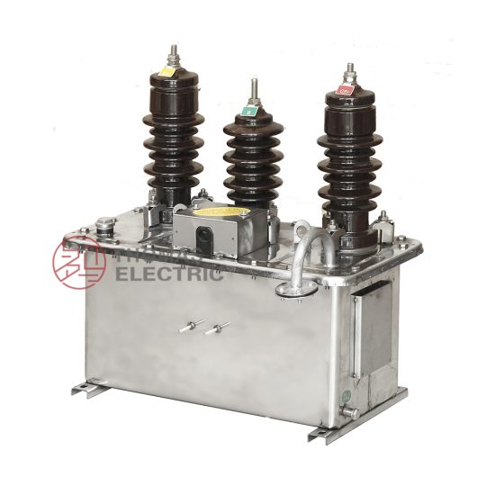
The JLS-6 is a single-phase, cast-resin insulated voltage transformer (VT) engineered for high-accuracy metering and reliable protection functions in medium-voltage distribution systems operating at 11kV (IEC nominal) or 10kV (domestic Chinese system). Designed specifically for integration into ring main units (RMUs), compact substations, and switchgear assemblies, the JLS-6 leverages vacuum pressure impregnation (VPI) epoxy resin technology to deliver superior dielectric performance, environmental resilience, and long-term operational stability.
Operating Principle and Insulation Technology
Voltage transformers like the JLS-6 operate on the principle of electromagnetic induction, stepping down the primary system voltage (11kV) to standardized secondary values—typically 100 V or 100/√3 V—for use by meters, relays, and monitoring equipment. The core innovation lies in its insulation system: the primary and secondary windings, along with the grain-oriented electrical steel (GOES) core, are fully encapsulated in cycloaliphatic epoxy resin via VPI. This process eliminates air voids, suppresses partial discharges (<5 pC at 1.2 × Um/√3), and provides excellent tracking resistance (CTI > 600). Unlike oil-filled alternatives, the solid dielectric offers no fire hazard, requires no maintenance for fluid levels, and withstands seismic activity without leakage.
Advantages Over Oil-Immersed Designs
Cast-resin VTs such as the JLS-6 present distinct advantages in modern distribution networks. First, they are inherently maintenance-free—no oil sampling, degassing, or tank inspections are needed. Second, their compact footprint (typical height: 480 mm; diameter: 180 mm) enables direct mounting inside RMUs where space is constrained. Third, the epoxy matrix provides superior mechanical strength, resisting deformation under short-circuit electrodynamic forces. Additionally, the absence of flammable oil makes them ideal for indoor installations, urban substations, and environments with strict fire safety codes (e.g., IEC 62271-200). Thermal performance is also enhanced: the resin’s high thermal conductivity (≈0.8 W/m·K) ensures uniform heat dissipation, supporting continuous operation at ambient temperatures up to +40°C.
Typical Deployment Scenarios
The JLS-6 is predominantly deployed in 11kV/10kV distribution feeders requiring dual-function accuracy—simultaneously serving Class 0.2 or 0.5 metering circuits and 3P or 6P protection relays. Common applications include utility-owned RMUs in smart grid projects, industrial plant switchgear for energy billing and motor protection, and renewable interconnection points (e.g., solar farms) where precise voltage monitoring is critical for anti-islanding schemes. Its robust design also suits harsh environments: coastal areas (salt fog resistance per IEC 60068-2-52), high-altitude sites (up to 2000 m ASL without derating), and regions with wide temperature swings (–25°C to +40°C).
Technical Specifications
The JLS-6 voltage transformer is engineered to meet stringent electrical and environmental performance criteria. Below is a comprehensive specification table followed by detailed service condition parameters.
| Parameter | Value |
|---|---|
| Primary Rated Voltage (Up) | 11 kV (IEC); 10 kV (GB) |
| Secondary Rated Voltage (Us) | 100 V or 100/√3 V |
| Voltage Ratio | 11000/100 V or 11000/100/√3 V |
| Accuracy Classes | Metering: 0.2, 0.5; Protection: 3P, 6P |
| Rated Output (per burden) | 10–100 VA (configurable) |
| Insulation Level (LI/AC) | 75 kV / 28 kV (1 min) |
| Short-Time Withstand Current | Not applicable (VTs do not carry load current) |
| Partial Discharge Level | <5 pC at 1.2 × (11/√3) kV |
| Core Material | Grain-Oriented Electrical Steel (GOES), 0.3 mm thickness |
| Insulation System | VPI Cycloaliphatic Epoxy Resin |
| Ambient Temperature Range | –25°C to +40°C |
| Altitude Limit | ≤ 2000 m above sea level |
| Relative Humidity | ≤ 95% (non-condensing) |
Electrical Performance Parameters
The JLS-6 delivers exceptional voltage transformation fidelity. At rated frequency (50 Hz), the ratio error for a 0.2-class winding must remain within ±0.2%, while phase displacement is limited to ±10 minutes. For protection-class windings (3P/6P), composite error under rated burden and 5%–100% of rated voltage must not exceed 3% or 6%, respectively. Burden compatibility is critical: the transformer is tested with standard burdens (e.g., 30 VA at cos φ = 0.8 lagging). Exceeding rated output increases ratio error nonlinearly—e.g., at 120% burden, a 0.5-class unit may drift to ±0.7%. The insulation coordination follows IEC 60071: the lightning impulse withstand voltage (LIWV) is 75 kV (1.2/50 μs wave), and power frequency withstand is 28 kV RMS for 1 minute between live parts and earth.
Environmental and Mechanical Ratings
Designed for both indoor and outdoor use, the JLS-6 features a UV-stabilized resin housing with IP00 rating (intended for enclosure mounting). Mounting is via M12 threaded studs at the base, with creepage distance ≥25 mm/kV (i.e., ≥275 mm for 11kV), satisfying pollution degree 3 per IEC 60664-1. The thermal design ensures that under continuous 1.2 × Un overvoltage (a common transient in distribution networks), hotspot temperature remains below 120°C—well within Class E insulation limits. Weight is approximately 28 kg, facilitating manual handling during installation.
Typical Applications
The JLS-6 voltage transformer serves as a cornerstone component in diverse medium-voltage infrastructure, enabling accurate revenue metering and dependable protective relaying.
Substation Secondary Metering Systems
In 11kV/0.4kV distribution substations, the JLS-6 provides the reference voltage for kWh meters used in utility billing. Its 0.2-class accuracy ensures compliance with regulatory requirements (e.g., China’s DL/T 448). Installed on the 11kV busbar within the RMU, it feeds signals to multi-tariff meters via shielded twisted-pair cables (min. 2.5 mm² cross-section). Critical to performance is burden matching: if the total metering circuit impedance exceeds the VT’s rated VA, voltage drop induces billing errors. For example, a 30 VA, 0.2-class JLS-6 connected to three meters (total burden 25 VA) maintains ±0.18% error—within tolerance. Misapplication (e.g., using a 10 VA unit for the same load) would cause significant under-registration.
Industrial Power Distribution Monitoring
Large manufacturing facilities deploy JLS-6 units to monitor feeder voltage for process control and energy management. In a steel mill, for instance, voltage sags below 90% Un can disrupt arc furnace operations. The JLS-6’s 6P protection winding triggers undervoltage relays within 20 ms, initiating load shedding. Simultaneously, its metering winding interfaces with SCADA systems for real-time voltage profiling. The cast-resin construction resists electromagnetic interference from nearby high-current busbars—a common issue with oil-filled VTs whose tanks act as antennas.
Renewable Energy Integration Points
Solar photovoltaic (PV) plants connecting to 11kV grids rely on JLS-6 VTs for grid-code compliance. Functions include voltage ride-through monitoring (per GB/T 19964), reactive power control, and anti-islanding detection. During cloud transients, rapid voltage fluctuations must be captured accurately; the JLS-6’s low phase displacement (<5 minutes at 0.5 class) ensures synchrophasor measurements remain coherent. Its compact size allows co-location with inverters in pad-mounted enclosures, reducing cabling costs and signal degradation.
Rural and Suburban Distribution Networks
In remote areas with long feeders, voltage regulation is challenging. Utilities install JLS-6 VTs at strategic poles to feed voltage regulators and capacitor banks. The transformer’s ability to operate reliably at –25°C prevents brittle fracture of insulation—a failure mode observed in older polyester-resin designs. Furthermore, its immunity to moisture ingress eliminates seasonal accuracy drift seen in open-frame VTs, ensuring consistent billing across monsoon and dry seasons.
Compliance with International Standards
The JLS-6 is certified to both global and Chinese national standards, ensuring interoperability and regulatory acceptance.
IEC 61869-3 Certification Details
IEC 61869-3 specifies performance, testing, and marking requirements for inductive voltage transformers. The JLS-6 complies fully with Clause 6 (rated values), Clause 7 (accuracy classes), and Clause 10 (type tests). Key verifications include: ratio error and phase displacement measured per IEC 61869-3 Annex B using precision bridges; temperature rise test (ΔT ≤ 55 K for resin); and impulse voltage test with 15 shots (positive/negative polarity). Markings on the nameplate include: “IEC 61869-3”, accuracy class per winding, rated output, and insulation level (e.g., “75/28”). Type test reports are issued by accredited labs (e.g., KEMA, CESI) and remain valid for five years.
Alignment with GB/T 20840.3
GB/T 20840.3 is China’s adoption of IEC 61869-3, with minor national deviations. The JLS-6 meets all GB-specific requirements, including: domestic voltage rating (10kV instead of 11kV), mandatory CCC certification, and additional short-time overvoltage endurance (1.9 × Un for 8 hours). While IEC permits 100/√3 V secondaries for grounded systems, GB/T 20840.3 explicitly requires this configuration for 10kV networks with resonant grounding. The JLS-6 is factory-configured accordingly, with secondary terminals labeled “da-dn” per GB conventions.
Harmonization and Testing Protocols
Differences between IEC and GB standards are largely administrative. Electrically, both mandate identical accuracy envelopes and insulation levels. However, GB/T 20840.3 adds a requirement for salt fog testing (IEC 60068-2-52, severity 6) for coastal deployments—a test the JLS-6 passes due to its hydrophobic resin surface. Routine tests per both standards include: visual inspection, winding resistance measurement (±2% tolerance vs. type test), and power frequency withstand at 80% of type test voltage (22.4 kV for 1 min).
On-Site Testing Procedures
Post-installation verification ensures the JLS-6 performs within specifications before energization.
Insulation Resistance Test
Using a 2500 V DC megohmmeter, measure insulation resistance between primary-to-secondary/ground and secondary-to-ground. Acceptance criterion: ≥1000 MΩ at 20°C. Correct for temperature using RT2 = RT1 × 2(T1–T2)/10. Values below 500 MΩ indicate moisture ingress or resin cracking—requiring drying or replacement. Perform before and after withstand voltage tests to detect insulation degradation.
Turns Ratio Test
Apply 100–200 V AC to the primary and measure secondary voltage with a calibrated voltmeter (accuracy class 0.1). Calculate actual ratio: Up/Us. Tolerance: ±0.2% for 0.2-class, ±0.5% for 0.5-class. Example: for 11000/100 V, measured secondary should be 100.00 ± 0.20 V at 110 V primary. Use low-voltage excitation to avoid core saturation.
Polarity Verification
Confirm reducing polarity (standard for IEC/GB VTs). Connect primary terminal “A” to secondary terminal “a” via a jumper. Apply 50 V AC between “X” (primary earth) and “x” (secondary earth). Measure voltage between “A” and “a”: it should equal |Up – Us|. If ≈Up + Us, polarity is additive—indicating incorrect internal wiring.
Power Frequency Withstand Voltage Test
Apply 22.4 kV RMS (80% of 28 kV type test) at 50 Hz between primary and grounded secondary/frame for 1 minute. Monitor for flashover, excessive leakage current (>1 mA), or audible discharge. Use a current-limiting resistor (5–10 kΩ) in series. Failure indicates compromised insulation—often due to shipping damage or improper handling.
Open-Circuit Characteristic Test
With secondary open, gradually increase primary voltage from 0 to 1.5 × Un (16.5 kV). Record excitation current. A sharp current rise below 1.2 × Un suggests core defects or shorted turns. At 1.0 × Un, excitation current should be ≤0.5% of rated primary current (≈0.03 A for 11kV/100V). This test validates magnetic circuit integrity.
Preventive Maintenance Guide
Though cast-resin VTs are maintenance-free, periodic checks extend service life and prevent unexpected failures.
Annual Visual and Electrical Inspection
Inspect for: surface cracks, tracking marks, terminal corrosion, or loose hardware. Clean housing with dry cloth—never solvents. Re-measure insulation resistance and compare to baseline. A 30% drop warrants investigation. Verify secondary wiring tightness (torque: 2.5 N·m for M6 terminals). Check for overheating signs (discoloration near terminals)—indicative of high contact resistance or overload burden.
Five-Year Comprehensive Assessment
Every 60 months, perform full requalification: repeat all on-site tests (ratio, polarity, withstand). Additionally, conduct partial discharge measurement using IEC 60270 methods—if PD exceeds 10 pC at 1.2 × Un/√3, internal voids may have developed. Review historical data: consistent ratio error drift suggests aging insulation. Replace if error exceeds 150% of original tolerance (e.g., >±0.3% for 0.2-class).
Maintenance Intervals and Fault Diagnosis
| Interval | Action | Fault Indicator |
|---|---|---|
| Annually | Visual check, IR test | Cracks, IR < 500 MΩ |
| 3 Years | Burden verification | Metering discrepancy >0.5% |
| 5 Years | Full electrical retest | Ratio error out of spec |
| As Needed | Thermal imaging | Hotspot >70°C at terminals |
Common faults include secondary short-circuits (causing core saturation and overheating) and moisture-induced surface leakage (evidenced by carbon tracking). Never operate with secondary open during primary energization—this induces dangerous overvoltages.
Conclusion
The JLS-6 11kV cast-resin voltage transformer represents a benchmark in medium-voltage instrumentation, combining metrological precision with rugged reliability for dual metering and protection roles. Its VPI epoxy resin encapsulation eliminates the fire risk and maintenance burden associated with oil-immersed alternatives, while the GOES core ensures minimal losses and stable accuracy across temperature and voltage variations. Full compliance with IEC 61869-3 and GB/T 20840.3 guarantees global acceptance and seamless integration into existing infrastructure—from urban RMUs to remote renewable sites. With a design life exceeding 25–30 years under standard service conditions, the JLS-6 delivers exceptional lifecycle value. Its rigorous factory and field testing protocols further ensure that performance remains within tight tolerances throughout decades of operation, making it a trusted choice for utilities and industrial operators demanding uncompromising accuracy and dependability in critical voltage measurement applications.