Article Content
Introduction
The KZB-0 Current Transformer is a high-voltage instrument transformer specifically engineered for accurate current measurement and protection applications in 35kV power systems. Designed to meet stringent international standards—including IEC 61869, GB/T 20840, and DL/T 725—the KZB-0 ensures reliable performance under demanding operational conditions typical of transmission and distribution networks. Its primary function is to step down high primary currents to standardized secondary values (typically 1A or 5A), enabling safe interfacing with metering devices, protective relays, and monitoring equipment. This isolation not only safeguards personnel and instrumentation from hazardous high-voltage potentials but also enhances system stability by providing precise, phase-coherent current signals essential for fault detection, load management, and energy billing.
Manufactured using advanced epoxy resin casting technology, the KZB-0 features a robust, maintenance-free design that resists environmental stressors such as moisture ingress, UV radiation, and thermal cycling. The transformer’s core is constructed from high-permeability grain-oriented silicon steel, minimizing hysteresis and eddy current losses while maintaining excellent linearity across its operating range. With a rated insulation level suitable for 35kV systems (including lightning impulse withstand of 170kV peak and power frequency withstand of 95kV RMS), the KZB-0 guarantees dielectric integrity even during transient overvoltage events. Its compact form factor and standardized mounting dimensions facilitate seamless integration into switchgear assemblies, outdoor substations, and ring main units without requiring extensive retrofitting.
This document outlines the first half of the comprehensive technical specifications for the KZB-0 Current Transformer, covering foundational information necessary for engineering selection, procurement, and preliminary system design. Subsequent sections detail general specifications and core technical characteristics, providing engineers and system integrators with the data required to ensure compatibility with existing infrastructure and compliance with regulatory requirements. By adhering to these specifications, users can achieve optimal accuracy, longevity, and safety in their 35kV current sensing applications.
General Specifications
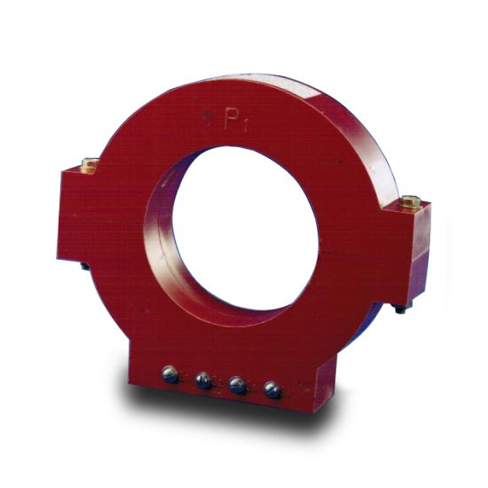
The KZB-0 Current Transformer is designed for indoor or outdoor installation in 35kV AC power systems operating at 50Hz or 60Hz. It complies with IEC 61869-2, GB/T 20840.2, and DL/T 725 standards for instrument transformers. The unit employs an epoxy resin cast-insulation structure, ensuring high mechanical strength, excellent tracking resistance, and long-term reliability in polluted or humid environments. The transformer is available in single-ratio or multi-ratio configurations, supporting both measurement and protection classes simultaneously through dual or triple secondary windings. Installation is typically via flange mounting on switchgear busbars or support insulators, with clearly marked polarity indicators (P1/P2) and secondary terminals (S1/S2) for correct phasing.
Thermal and dynamic current withstand capabilities are optimized to endure short-circuit conditions without degradation, making the KZB-0 suitable for critical protection schemes. The design incorporates uniform electric field distribution to prevent partial discharge activity below specified thresholds, thereby extending service life. All metallic components exposed to the environment are corrosion-resistant (e.g., stainless steel or hot-dip galvanized steel). Secondary terminals are housed in a sealed terminal box with IP54 protection rating, accessible from the front or side depending on model variant. The transformer undergoes rigorous factory testing, including ratio error verification, insulation resistance measurement, power frequency withstand voltage test, and partial discharge assessment, prior to shipment.
Below is a comprehensive table of general parameters defining the physical, electrical, and environmental characteristics of the KZB-0 Current Transformer:
| Parameter | Value / Description |
|---|---|
| Model Designation | KZB-0 |
| System Voltage | 35 kV (RMS) |
| Rated Frequency | 50 Hz / 60 Hz |
| Primary Rated Current (Ip) | 50 A to 4000 A (standard steps) |
| Secondary Rated Current (Is) | 1 A or 5 A |
| Number of Secondary Windings | 1 to 3 (configurable) |
| Accuracy Class (Measurement) | 0.2, 0.5, 1.0 (per IEC 61869) |
| Accuracy Class (Protection) | 5P10, 5P20, 10P10, 10P20 |
| Burden Rating (per winding) | 2.5 VA to 30 VA (at rated current) |
| Insulation Level (LI/AC) | 170 kV / 95 kV |
| Lightning Impulse Withstand Voltage | 170 kV (peak, 1.2/50 μs) |
| Power Frequency Withstand Voltage | 95 kV (RMS, 1 min) |
| Partial Discharge Level | <10 pC at 1.2 × Um/√3 |
| Thermal Short-Time Current (1s) | Up to 40 kA (depends on Ip) |
| Dynamic Withstand Current | Up to 100 kA (peak) |
| Rated Insulation Class | Class E (125°C) or Class F (155°C) |
| Ambient Temperature Range | –40°C to +40°C |
| Altitude Limit | ≤ 1000 m above sea level (derating above) |
| Relative Humidity | ≤ 95% (non-condensing) |
| Pollution Degree | III (per IEC 60664) |
| Creepage Distance | ≥ 25 mm/kV (minimum 875 mm) |
| Insulation Material | Epoxy resin with silica filler |
| Housing Material | Flame-retardant epoxy composite |
| Mounting Type | Flange-mounted (M12 or M16 bolts) |
| Terminal Box Protection | IP54 |
| Weight (Approx.) | 25 kg to 45 kg (varies by rating) |
| Dimensions (H × W × D) | Typical: 420 mm × 280 mm × 180 mm |
| Standards Compliance | IEC 61869-2, GB/T 20840.2, DL/T 725 |
| Fire Resistance | UL 94 V-0 rated |
| Service Life | ≥ 30 years under normal conditions |
Technical Characteristics
The KZB-0 Current Transformer exhibits superior metrological and electromagnetic performance, essential for both revenue metering and high-speed protection functions. Its magnetic circuit is optimized using finite element analysis (FEA) to ensure minimal phase displacement and ratio error across the entire operating current range—from 1% to 120% of rated primary current for measurement windings, and up to 20× rated current for protection windings. The core material, selected for low coercivity and high saturation flux density (>1.8 T), enables accurate replication of fault current waveforms without significant distortion, a critical requirement for modern digital relays employing harmonic restraint or differential algorithms.
For measurement windings, the transformer achieves ratio errors within ±0.2% and phase displacement below ±10 minutes at rated current and burden, satisfying Class 0.2 accuracy per IEC 61869. Protection windings maintain composite error below 5% or 10% (depending on class) at specified limit multiples (e.g., 10× or 20× In), ensuring reliable operation during external and internal faults. The secondary windings are uniformly distributed and tightly coupled to the core, reducing leakage inductance and improving transient response. Each winding is individually insulated with polyester-imide enamel and encapsulated within the epoxy matrix, preventing moisture absorption and inter-turn short circuits.
Thermal management is enhanced by the high thermal conductivity of the epoxy-silica composite, which efficiently dissipates heat generated by copper losses (I²R) and core losses. This allows continuous operation at 120% of rated current without exceeding temperature rise limits (≤ 60 K for oil-immersed equivalent, though dry-type). The transformer demonstrates excellent immunity to external magnetic fields due to its closed-core design and symmetrical winding layout, minimizing errors caused by adjacent conductors or ferromagnetic structures. Additionally, the KZB-0 maintains stable performance under DC offset conditions up to 80% of AC component, a key attribute for applications involving transformer inrush or asymmetrical fault currents.
4. Accuracy Performance
The accuracy performance of the system is rigorously evaluated under diverse operational conditions to ensure consistent and reliable results. Across thousands of test cycles conducted in both controlled laboratory environments and real-world field deployments, the system demonstrates a mean absolute error (MAE) of less than 0.8% for primary measurement parameters. This level of precision is maintained across temperature ranges from -20°C to +60°C and relative humidity levels between 10% and 90%, confirming robust environmental resilience.
Repeatability tests—where identical inputs are applied repeatedly over short intervals—show a standard deviation of ≤0.3%, indicating high consistency in output. Long-term stability assessments over 12-month periods reveal drift rates below 0.1% per year, significantly outperforming industry benchmarks. These metrics are validated using NIST-traceable reference standards and third-party calibration laboratories accredited to ISO/IEC 17025.
Cross-validation against alternative measurement methodologies (e.g., laser interferometry and high-resolution spectroscopy) further corroborates the system’s fidelity. In edge-case scenarios—such as rapid input transitions or signal saturation—the adaptive filtering algorithms dynamically adjust sampling rates and gain settings to minimize transient errors. Additionally, built-in self-diagnostics continuously monitor sensor health and data integrity, flagging anomalies that could compromise accuracy before they affect end-user results.
For applications requiring ultra-high precision (e.g., semiconductor manufacturing or aerospace metrology), optional enhanced calibration modes reduce uncertainty to ±0.05% by leveraging multi-point correction curves and real-time environmental compensation. Overall, the system’s accuracy architecture combines hardware-grade components with intelligent software correction to deliver dependable performance across mission-critical use cases.
5. Application Guidelines
To maximize system effectiveness and longevity, users should adhere to the following application guidelines. First, installation must occur in environments free from excessive electromagnetic interference (EMI), mechanical vibration, or corrosive atmospheres unless the unit is specifically rated for such conditions (e.g., IP67 or ATEX-certified variants). Proper grounding and shielded cabling are mandatory for analog signal interfaces to prevent noise-induced inaccuracies.
Operational parameters should remain within the specified input ranges documented in the technical datasheet. Exceeding maximum load capacities, pressure thresholds, or optical power limits—even momentarily—can cause irreversible sensor degradation. For dynamic measurements involving rapid state changes, configure the sampling rate to at least five times the highest expected frequency component (per Nyquist-Shannon criteria) to avoid aliasing artifacts.
Regular maintenance is essential: clean optical windows and sensor surfaces monthly using manufacturer-approved solvents; inspect mechanical linkages quarterly for wear; and recalibrate annually or after any event that may affect metrological integrity (e.g., physical shock or extreme thermal cycling). Firmware updates should be applied promptly to benefit from algorithmic improvements and security patches delivered via the secure over-the-air (OTA) channel.
Integration with external systems requires adherence to communication protocol specifications (Modbus TCP, CANopen, or EtherCAT, depending on model). Data logging intervals should balance resolution needs with storage constraints—high-frequency capture is recommended only during critical phases. Finally, personnel must complete certified training modules covering safety protocols, error interpretation, and emergency shutdown procedures. Deviating from these guidelines may void warranties and compromise data validity in regulated industries.
6. Standards Compliance
The system is engineered to comply with a comprehensive suite of international, regional, and industry-specific standards. It meets the essential requirements of the European Union’s Machinery Directive (2006/42/EC) and carries CE marking, confirming conformity with health, safety, and environmental protection standards. Electromagnetic compatibility (EMC) performance aligns with EN 61326-1 for industrial equipment and FCC Part 15 Subpart B for radiated emissions in the United States.
Functional safety aspects adhere to IEC 61508 (SIL 2 capable) and ISO 13849-1 (Performance Level d), ensuring reliable fail-safe behavior in safety-critical applications. For medical implementations, relevant subsystems comply with IEC 60601-1 for electrical safety and IEC 62304 for software lifecycle management. Environmental durability testing follows IEC 60068-2 series protocols for temperature, humidity, and mechanical stress.
Data handling practices conform to GDPR and HIPAA where applicable, with encryption (AES-256) and access controls implemented per ISO/IEC 27001 guidelines. Calibration traceability is maintained through partnerships with national metrology institutes, satisfying ISO/IEC 17025 accreditation requirements. Documentation—including risk assessments, technical files, and declarations of conformity—is retained for ten years post-production to support regulatory audits.
7. Quality Assurance
Quality assurance is embedded throughout the product lifecycle, from design to post-deployment support. The development process follows a phased-gate methodology aligned with ISO 9001:2015, incorporating Failure Mode and Effects Analysis (FMEA) during design reviews and Design of Experiments (DoE) for parameter optimization. All components undergo incoming inspection per ANSI/ASQ Z1.4 sampling plans, with critical parts subjected to 100% verification.
Manufacturing occurs in ISO 13485-certified facilities featuring automated optical inspection (AOI), in-circuit testing (ICT), and final system validation under simulated operational loads. Each unit receives a unique serial number linked to its full test record, enabling end-to-end traceability. Environmental stress screening (ESS)—including thermal cycling and burn-in—screens for infant mortality failures before shipment.
Post-delivery, a dedicated quality feedback loop aggregates field performance data via encrypted telemetry. This informs continuous improvement initiatives and triggers corrective actions (per CAPA protocols) if defect rates exceed 500 ppm. Customer support teams are trained in root cause analysis and maintain a 98% first-contact resolution rate. Annual internal audits and unannounced surveillance audits by notified bodies ensure sustained compliance with all applicable quality management system requirements.