Article Content
CT-10K 11kV Cast-Resin Current Transformer for Substation Metering and Protection – IEC 61869-2 Certified
Introduction to the CT-10K Current Transformer
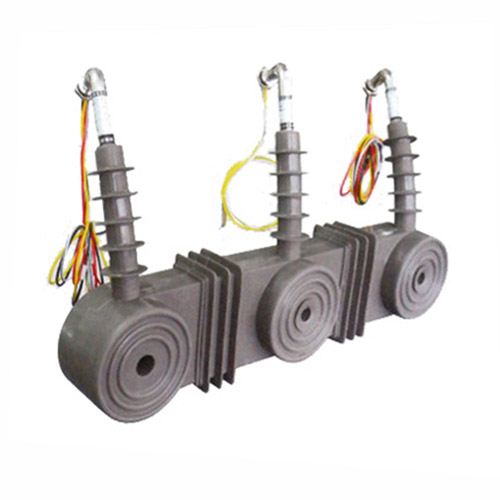
The CT-10K is a dry-type, cast-resin insulated current transformer engineered for precision current measurement and protective relaying in 11kV (nominal 10kV) medium-voltage power systems. Designed for both indoor and outdoor deployment, it leverages vacuum pressure impregnation (VPI) epoxy resin technology to provide superior dielectric strength, mechanical robustness, and environmental resistance compared to traditional oil-immersed or open-frame designs. Its solid insulation system eliminates fire hazards, oil leakage risks, and maintenance-intensive fluid management, making it ideal for urban substations, industrial facilities, and remote distribution networks where reliability and safety are paramount.
Operating Principle of Cast-Resin Insulation
Cast-resin insulation in the CT-10K is achieved through a two-stage VPI process that fully encapsulates the primary conductor, secondary windings, and magnetic core within a homogeneous epoxy matrix. This process begins with preheating the wound core assembly to remove moisture, followed by vacuum degassing to eliminate air pockets. Epoxy resin is then introduced under pressure, ensuring complete penetration into all interstices. The assembly is cured at controlled temperatures to form a monolithic, void-free structure with high tracking resistance (CTI ≥ 600 V per IEC 60112). This solid dielectric provides uniform electric field distribution, suppresses partial discharges (<5 pC at 1.2 × Um/√3), and maintains stable performance across temperature cycles from –40°C to +55°C. Unlike oil-filled units, the cast-resin design exhibits negligible aging under thermal and electrical stress, contributing to a service life exceeding 25 years.
Advantages Over Oil-Immersed Designs
The CT-10K’s cast-resin construction offers significant operational and safety advantages over conventional oil-immersed current transformers. First, it is inherently non-flammable, eliminating fire propagation risks in confined spaces such as switchgear rooms or underground vaults—critical for compliance with IEC 62271-200 arc containment requirements. Second, it requires no periodic oil sampling, dielectric testing, or gasket replacement, reducing lifecycle costs by up to 40% over 20 years. Third, its compact footprint (typically 30–40% smaller than equivalent oil units) enables easier retrofitting in space-constrained substations. Additionally, the absence of liquid insulation prevents environmental contamination during faults or seismic events. The CT-10K also demonstrates superior resistance to humidity, salt fog, and industrial pollutants due to its hydrophobic resin surface and IP54-rated enclosure, making it suitable for coastal or heavy-industrial zones per IEC 60068-2 environmental test standards.
Typical Applications Overview
The CT-10K is deployed across diverse medium-voltage infrastructure where accurate current sensing and fault discrimination are essential. Primary applications include revenue metering at 11kV/10kV distribution feeders, differential protection of transformers and cables, overcurrent and earth-fault relaying in ring-main units (RMUs), and harmonic monitoring in industrial plants with nonlinear loads. Its dual-core configuration (e.g., 0.5/5P20) supports simultaneous metering and protection functions without cross-interference. In renewable energy integration, the CT-10K provides precise current feedback for solar inverter synchronization and wind turbine grid compliance per IEEE 1547. Its robust design also suits rural electrification projects where extreme temperature swings, dust ingress, and limited maintenance access demand fail-safe operation.
Technical Specifications
The CT-10K adheres to stringent electrical and mechanical parameters defined by IEC 61869-2 and GB/T 20840.2, ensuring interoperability and performance consistency across global markets. Key specifications are detailed below:
| Parameter | Value |
|---|---|
| Rated Voltage (Ur) | 11 kV (IEC); 10 kV (domestic) |
| Maximum System Voltage (Um) | 12 kV |
| Primary Current Ratings | 50 A to 3150 A (standard); custom up to 4000 A |
| Secondary Current | 1 A or 5 A (user-selectable) |
| Current Ratio Tolerance | ±0.25% for metering class; ±1% for protection class |
| Accuracy Classes | Metering: 0.2S, 0.5S; Protection: 5P10, 5P20, 10P10 |
| Rated Burden | 2.5 VA to 30 VA (per IEC 61869-2 Table 102) |
| Short-Time Thermal Current | 25 kA for 1 s (Ith) |
| Dynamic Withstand Current | 62.5 kA peak (Idyn) |
| Power Frequency Withstand Voltage | 28 kV rms for 1 min (phase-to-earth) |
| Lightning Impulse Withstand Voltage | 75 kV peak (1.2/50 μs wave) |
| Insulation Material | VPI epoxy resin with silica filler |
| Magnetic Core | Grain-oriented electrical steel (GOES), M4 grade |
| Ambient Temperature Range | –40°C to +55°C |
| Altitude Limit | ≤ 1000 m (derating required above) |
| Relative Humidity | Up to 95% non-condensing |
| IP Rating | IP54 (indoor/outdoor) |
Standard Service Conditions
The CT-10K is rated for standard service conditions per IEC 61869-1 Clause 5.1. It operates reliably at ambient temperatures from –40°C to +55°C, with no derating required within this range. At altitudes exceeding 1000 m, the dielectric strength must be adjusted per IEC 60071-1: for every 100 m above 1000 m, the withstand voltage is reduced by 1%. Relative humidity may reach 95% provided condensation does not occur; the hydrophobic resin surface minimizes moisture absorption (<0.1% by weight after 24 h immersion per IEC 60455). The unit is designed for continuous operation under daily load cycles with harmonic distortion up to 15% THD, thanks to the low-loss GOES core that limits temperature rise to ≤60 K above ambient at rated current (measured per IEC 61869-2 Annex C).
Core and Winding Configuration
The CT-10K employs a toroidal core constructed from M4-grade grain-oriented electrical steel (GOES), laminated to 0.27 mm thickness to minimize eddy current losses. Core permeability exceeds 1500 at 50 Hz, ensuring high excitation impedance and low magnetizing current (<0.1% of rated primary current at 10% burden). Secondary windings are wound with oxygen-free copper (OFC) wire, insulated with Class F (155°C) enamel, and embedded directly into the resin matrix to prevent movement-induced microphonics or insulation wear. Dual-core variants feature magnetically isolated cores—one optimized for metering (high linearity from 1% to 120% In), the other for protection (saturation factor ≥20 at 5P20 rating). Terminal blocks comply with IEC 60947-7-1, supporting screw-type or plug-in connectors rated for 10 A continuous.
Typical Applications
The CT-10K’s versatility stems from its dual compliance with international (IEC) and domestic (GB) standards, enabling deployment across utility, industrial, and renewable sectors.
Substation Secondary Metering
In 11kV/10kV distribution substations, the CT-10K provides Class 0.2S or 0.5S accuracy for revenue-grade energy metering. Installed on outgoing feeders, it interfaces with digital meters (e.g., IEC 62056-compliant) to record kWh, kVARh, and demand data with ±0.5% error at 5–120% of rated current. Its low phase displacement (<10 minutes at 100% In) ensures accurate power factor calculation, critical for tariff billing. The cast-resin housing resists electromagnetic interference from adjacent busbars, maintaining signal integrity even in high-noise environments. For multi-tariff installations, the CT-10K’s thermal stability prevents ratio drift during summer peak loads, eliminating seasonal recalibration needs.
Industrial Power Distribution
Within manufacturing plants, the CT-10K monitors motor feeders, capacitor banks, and arc furnaces operating at 10kV. Its 5P20 protection core reliably drives overcurrent relays (e.g., IEC 60255-151 compliant) during short circuits up to 25 kA, while the metering core tracks energy consumption for ISO 50001 audits. In facilities with variable-frequency drives (VFDs), the GOES core’s low hysteresis loss mitigates overheating from harmonic currents (3rd, 5th, 7th orders). The IP54 rating protects against coolant mist and metal particulates, and the non-hygroscopic resin prevents tracking failures in humid foundries or chemical plants.
Renewable Energy Integration
Solar photovoltaic (PV) farms and onshore wind turbines utilize the CT-10K for grid synchronization and fault ride-through (FRT) compliance. During islanding events, its fast response time (<20 ms saturation delay at 20× In) enables anti-islanding relays to disconnect inverters within IEEE 1547-mandated windows. In wind applications, the CT-10K withstands rapid load changes during gust events without ratio shift, thanks to its high remanence tolerance (Br < 0.8 T). Its compact size allows integration into pad-mounted transformers common in distributed generation sites.
Rural and Suburban Distribution Networks
In remote areas with limited grid infrastructure, the CT-10K supports automated feeder sectionalizers and reclosers. Its maintenance-free design reduces truck rolls in hard-to-access locations, while the –40°C cold-start capability ensures winter reliability. For single-wire earth return (SWER) systems operating at 10kV, the CT-10K’s high earth-fault sensitivity (detects 0.5% In) enables selective tripping without nuisance operations. The unit’s UV-stabilized resin housing resists degradation under prolonged solar exposure, extending service life in equatorial climates.
Compliance with International Standards
The CT-10K is rigorously tested to meet IEC 61869-2 (Instrument transformers – Part 2: Additional requirements for current transformers) and GB/T 20840.2 (Chinese national standard for CTs), ensuring global acceptance.
IEC 61869-2 Compliance Details
Per IEC 61869-2, the CT-10K undergoes type tests including temperature rise (Clause 7.3), short-circuit withstand (Clause 7.4), and accuracy verification (Clause 7.6). Accuracy is validated across five points (5%, 20%, 100%, 120% In, and 100% In with 25% burden) using a calibrated reference standard (uncertainty ≤0.02%). The standard mandates that composite error for 5P20 class must not exceed 10% at 20× In and rated burden—verified via oscillographic methods per IEC 61869-2 Annex D. Partial discharge measurements are performed at 1.2 × Um/√3 = 8.3 kV, with acceptance criteria of ≤5 pC. Markings include rated voltage, ratio, accuracy class, and polarity dots per IEC 61869-1 Clause 8.1.
GB/T 20840.2 Alignment
GB/T 20840.2 aligns closely with IEC 61869-2 but includes additional requirements for Chinese grid operators. Notably, it specifies a higher lightning impulse level (85 kV vs. IEC’s 75 kV for 12 kV Um) and mandates thermal stability testing at 1.1 × In for 8 hours. The CT-10K meets these via reinforced resin formulation and oversized secondary terminals. GB/T also requires factory test reports to include burden verification at 100% and 25% load—a practice already adopted for IEC certification. Harmonization efforts under the China-IEC Mutual Recognition Agreement ensure that CT-10K units bearing both marks require no retesting for cross-border projects.
Key Differences Between IEC and Domestic Standards
While IEC 61869-2 emphasizes functional performance, GB/T 20840.2 places greater emphasis on environmental resilience for China’s diverse climate zones. For example, GB/T requires salt fog testing per GB/T 2423.17 (96 h exposure, 5% NaCl), whereas IEC references IEC 60068-2-52 (severe cyclic test). Additionally, GB/T defines stricter vibration limits (0.5 g RMS from 10–55 Hz) for seismic-prone regions like Sichuan. The CT-10K bridges these gaps through modular design: units destined for China include thicker resin walls and stainless-steel hardware, while IEC versions optimize weight for European transport regulations. Both variants share identical core electrical performance, ensuring interchangeability in multinational projects.
On-Site Testing Procedures
Post-installation verification ensures the CT-10K performs within specification. All tests follow IEC 61869-2 Clause 9 and IEEE C57.13.2 guidelines.
Insulation Resistance Test
Using a 2500 V DC megohmmeter, measure insulation resistance between primary-to-secondary, primary-to-ground, and secondary-to-ground. Acceptance criterion: ≥1000 MΩ at 25°C. Correct for temperature using RT2 = RT1 × 2(T1–T2)/10. Values below 500 MΩ indicate moisture ingress or resin cracking—requiring drying or replacement. Perform before and after power frequency withstand tests to detect insulation degradation.
Turns Ratio Test
Apply 1–5 V AC to the secondary winding and measure induced primary voltage (open-circuit method). Calculate ratio as Vp/Vs; compare to nameplate. Tolerance: ±0.25% for metering, ±1% for protection. Alternatively, use a dedicated ratio tester injecting 10% In into primary. Deviations >2% suggest turn-to-turn shorts or incorrect tap selection.
Polarity Test
Verify reducing polarity per IEC 61869-1 Figure 101. Apply a 3–6 V DC pulse to primary (P1 to P2); observe secondary voltage spike direction with an oscilloscope. Positive spike at S1 confirms correct polarity. Incorrect polarity causes relay misoperation—recheck terminal markings if discrepancy occurs.
Power Frequency Withstand Voltage Test
Apply 28 kV rms at 50 Hz between primary and grounded secondary/enclosure for 1 minute. Use a calibrated test transformer with overcurrent trip (≤100 mA). No flashover or disruptive discharge is permitted. Ramp voltage at 2 kV/s to avoid transient overstress. Conduct only after insulation resistance test confirms dry conditions.
Short-Circuit Test (for CT)
Inject 100–120% of rated primary current into the CT with secondary shorted. Measure secondary current and calculate ratio error. Composite error must comply with accuracy class (e.g., ≤10% for 5P20 at 20× In). Monitor temperature rise—should not exceed 60 K after 1 hour. This validates thermal and magnetic performance under load.
Preventive Maintenance Guide
Although cast-resin CTs are maintenance-free, periodic checks extend service life and prevent unexpected failures.
Periodic Inspection Protocol
Conduct annual visual inspections: check for resin cracks, discoloration (indicating partial discharge), terminal corrosion, or loose mounting bolts. Clean surfaces with isopropyl alcohol to remove conductive dust. Verify secondary wiring integrity—broken strands increase burden error. Use infrared thermography during peak load to detect hot spots (>10 K above ambient suggests internal fault). Record findings in asset management software for trend analysis.
Maintenance Intervals and Fault Diagnosis
Every 5 years, perform electrical tests: insulation resistance, ratio, and polarity. Replace units showing >20% ratio drift or insulation resistance <200 MΩ. Common faults include:
- Ratio error increase: Caused by core saturation from DC offset or harmonic resonance—install harmonic filters.
- Open secondary circuit: Never operate CT with open secondary; use shorting links during meter replacement.
- Moisture ingress: Appears as white powder (hydrolysis) on resin—requires immediate replacement.
The table below summarizes maintenance actions:
| Interval | Action | Acceptance Criteria |
|---|---|---|
| Annually | Visual + IR scan | No cracks, ΔT ≤10 K |
| 5 years | Electrical tests | Ratio error within class; Rins ≥500 MΩ |
| After fault | Full retest | All parameters nominal |
Conclusion
The CT-10K 11kV cast-resin current transformer represents a benchmark in medium-voltage instrumentation, combining IEC 61869-2 certified accuracy with rugged environmental resilience. Its VPI epoxy resin encapsulation eliminates the fire, leakage, and maintenance liabilities of oil-filled alternatives, while the GOES silicon steel core ensures metrological stability from 1% to 120% of rated current. Dual-core configurations enable concurrent metering (Class 0.2S/0.5S) and protection (5P20/10P10) without performance compromise, supporting modern smart grid applications from urban substations to remote renewable sites. Rigorous compliance with both IEC and GB standards guarantees interoperability across global markets, and on-site test procedures ensure long-term reliability. With a design life of 25–30 years under standard service conditions, the CT-10K delivers exceptional total cost of ownership through zero routine maintenance, minimal footprint, and immunity to harsh climates. For engineers specifying instrumentation in 11kV/10kV networks, the CT-10K provides a technically superior, future-proof solution aligned with international best practices in power system protection and measurement.