Article Content
CT-35K 33kV Cast-Resin Current Transformer for Substation Metering and Protection – IEC 61869-2 Certified
Introduction to the CT-35K Current Transformer
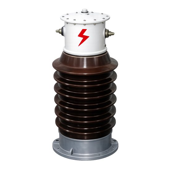
The CT-35K is a high-voltage, cast-resin insulated current transformer (CT) designed for accurate current measurement and dependable protective relaying in 33 kV (IEC-rated) medium-voltage networks, equivalent to domestic 35 kV systems. Engineered for both indoor and outdoor substations, this device leverages vacuum pressure impregnation (VPI) epoxy resin technology to provide superior dielectric strength, environmental resilience, and long-term operational stability. Unlike traditional oil-immersed CTs, the CT-35K eliminates fire hazards, oil leakage risks, and maintenance-intensive fluid management, making it ideal for urban substations, industrial facilities, and renewable energy interconnection points where safety and reliability are paramount.
Operating Principle of Cast-Resin Insulation
Cast-resin insulation in the CT-35K utilizes a thermosetting epoxy resin system cured under vacuum and pressure to fully encapsulate the primary conductor, magnetic core, and secondary windings. This process—known as Vacuum Pressure Impregnation (VPI)—ensures complete void-free encapsulation, preventing partial discharge inception even under sustained overvoltage conditions. The resin matrix provides a dielectric strength exceeding 20 kV/mm and exhibits excellent tracking resistance (CTI > 600), critical for outdoor installations exposed to pollution, humidity, and UV radiation. The homogeneous structure minimizes thermal stress during load cycling and offers a coefficient of thermal expansion closely matched to embedded metallic components, reducing mechanical fatigue over decades of service. Additionally, the solid insulation enables compact physical dimensions while maintaining required creepage distances per IEC 60815 for pollution severity levels up to III.
Advantages Over Oil-Immersed Designs
Compared to oil-filled counterparts, the CT-35K’s dry-type construction eliminates flammability risks, aligning with modern substation safety codes such as NFPA 70E and IEC 61936-1. There is no need for conservators, breathers, or oil sampling programs, significantly reducing lifecycle costs. The absence of liquid also prevents environmental contamination during faults or aging-related failures. Thermally, the epoxy resin has higher thermal conductivity (~0.8 W/m·K) than mineral oil, enabling better heat dissipation from the GOES (Grain-Oriented Electrical Steel) core during transient overloads. Furthermore, the CT-35K achieves a rated short-time thermal current of 20 kA for 1 second without degradation—performance comparable to oil units but with faster post-fault recovery and no risk of internal arcing due to gas formation. These attributes make the CT-35K particularly suitable for confined urban substations, data centers, and offshore wind farms where space, safety, and maintenance access are constrained.
Typical Applications Overview
The CT-35K is deployed across diverse 33/35 kV infrastructure segments. In utility transmission substations, it feeds revenue-grade metering circuits compliant with IEC 62053-22 Class 0.2S accuracy. In industrial plants, it interfaces with differential protection relays for motors and transformers, leveraging its 5P20 or 10P20 protection-class windings. Renewable integration sites—such as solar farms and onshore wind clusters—use the CT-35K to monitor grid export currents and enable anti-islanding protection schemes. Its robust design also supports deployment in rural distribution feeders where ambient temperatures range from -40°C to +55°C and altitudes exceed 2000 meters above sea level. Each application benefits from the transformer’s immunity to moisture ingress, stable ratio error over temperature, and resistance to mechanical vibration from nearby switching operations.
Technical Specifications
The CT-35K adheres to stringent electrical and mechanical parameters defined by IEC 61869-2 and GB/T 20840.2, ensuring interoperability across global grids. Key specifications include a highest voltage for equipment (Um) of 36 kV, corresponding to a 33 kV nominal system voltage (with 35 kV as the domestic Chinese equivalent). Standard current ratios range from 50/1 A to 3000/5 A, with dual or triple secondary windings available for combined metering and protection functions. Accuracy classes include 0.2S, 0.5S for metering, and 5P10, 5P20, 10P10, or 10P20 for protection duties. Rated outputs span 5 VA to 30 VA per winding, selected based on connected burden impedance.
Electrical and Insulation Parameters
The CT-35K features a power frequency withstand voltage of 70 kV RMS for 1 minute between primary and earth, and 3 kV RMS between secondary windings and earth, per IEC 61869-2 Table 2. Lightning impulse withstand voltage is rated at 170 kV peak (1.2/50 µs waveform). The partial discharge level is guaranteed below 10 pC at 1.2 × Um/√3 (24.9 kV), verified during factory testing. Insulation coordination includes a minimum creepage distance of 630 mm for pollution severity class III (equivalent to 25 mm/kV). The core is constructed from high-permeability GOES laminations (grade M4 or better), annealed to minimize hysteresis loss and ensure linear excitation characteristics up to 20× rated current. Ratio error tolerance for 0.2S class is ±0.2% at 20–120% of rated current, with phase displacement ≤ ±10 minutes. For protection classes, composite error at specified accuracy limit factor (e.g., 20 for 5P20) does not exceed 5%.
Environmental and Mechanical Ratings
Designed for operation in ambient temperatures from -40°C to +55°C, the CT-35K maintains performance within specification across this range without derating. Relative humidity tolerance extends to 100% non-condensing, supported by hydrophobic resin formulation. Altitude rating is standard up to 1000 m; for installations above this, derating factors per IEC 60071-2 apply (e.g., 1.13 correction factor at 2000 m). The housing is UV-stabilized cycloaliphatic epoxy resin, resistant to cracking under thermal cycling (-40°C to +80°C, 100 cycles). Mechanical load rating on primary terminals is 500 N in any direction, suitable for rigid busbar mounting. Secondary terminals are housed in an IP54-rated terminal box with stainless steel screws, accommodating 2.5–6 mm² copper conductors. Weight ranges from 28 kg (single ratio) to 42 kg (triple ratio), facilitating handling with standard lifting lugs.
Typical Applications
The CT-35K serves critical roles in modern power systems where precision, safety, and longevity are non-negotiable. Its cast-resin construction and dual-function windings enable versatile deployment across utility, industrial, and renewable sectors.
Substation Secondary Metering
In 33 kV transmission and distribution substations, the CT-35K provides input to revenue metering systems requiring IEC 62053-22 Class 0.2S compliance. For example, a dual-winding CT-35K may feature one 0.2S/5 VA winding feeding a smart meter for billing, and a second 5P20/15 VA winding connected to a distance relay for feeder protection. The low phase displacement (<5 minutes at 100% In) ensures accurate power factor calculation, critical for tariff structures involving reactive energy penalties. Installation on ring-main units (RMUs) or gas-insulated switchgear (GIS) bushings leverages the CT’s compact profile (diameter ≤ 280 mm), minimizing footprint in space-constrained urban substations. Long-term ratio stability—verified through accelerated aging tests per IEC 61869-2 Annex D—guarantees billing accuracy over 25+ years without recalibration.
Industrial Power Distribution
Heavy industries such as steel mills, petrochemical plants, and mining operations deploy the CT-35K on 35 kV motor feeders and transformer incomers. Here, the 10P20 protection winding withstands high fault currents (e.g., 20 kA symmetrical) while maintaining sufficient secondary voltage to drive electromechanical or digital relays through cable burdens up to 2 Ω. The transformer’s high saturation point (knee-point voltage ≥ 500 V for 5 A secondaries) prevents core saturation during motor starting inrush, which can reach 6–8× full-load current. In arc furnace applications, harmonic-rich currents (up to 13th order) are handled without significant heating due to the low-loss GOES core and distributed secondary winding design that mitigates eddy current losses. Maintenance teams benefit from the absence of oil, eliminating spill containment protocols during replacement.
Renewable Energy Integration
Solar photovoltaic (PV) farms and onshore wind parks operating at 33 kV grid connection voltages utilize the CT-35K for both performance monitoring and grid-code compliance. For instance, a 50 MW solar plant may install CT-35K units at the point of common coupling (PCC) to measure active/reactive power export for SCADA telemetry and to trigger under-frequency load shedding (UFLS) relays during islanding events. The CT’s fast response time (<20 ms to 90% of final value during step current changes) ensures timely relay operation per IEEE 1547-2018 requirements. In coastal wind farms, the UV-resistant, salt-fog-tested resin housing (per IEC 60068-2-52) prevents surface degradation, while the sealed terminal box excludes conductive dust that could cause secondary short circuits.
Rural and Suburban Distribution Networks
In remote or semi-urban 35 kV radial feeders, the CT-35K supports automated sectionalizing and fault location. Mounted on pole-top reclosers or pad-mounted switchgear, its robustness withstands wide diurnal temperature swings and occasional lightning surges. A typical configuration uses a single 0.5/10P10 winding: the metering section feeds a distribution transformer monitor (DTM) for load profiling, while the protection section triggers a recloser after 0.3 seconds for permanent faults. The CT’s low excitation current (<0.5% of In at rated voltage) minimizes burden on legacy electromechanical relays still in use in developing regions. Field experience in Southeast Asia and Africa confirms >99.5% operational availability over 10-year deployments, attributed to the resin’s resistance to termite damage and fungal growth.
Compliance with International Standards
The CT-35K is certified to IEC 61869-2:2012 (“Instrument transformers – Part 2: Additional requirements for current transformers”) and GB/T 20840.2-2014 (“Instrument transformers – Part 2: Additional requirements for current transformers”), ensuring global acceptance. Compliance encompasses design verification, type testing, routine testing, and special tests as mandated by these standards.
IEC 61869-2 Certification Details
Under IEC 61869-2, the CT-35K undergoes rigorous validation including temperature rise tests (winding rise ≤ 60 K for resin-insulated CTs), short-circuit withstand tests (20 kA/1 s without deformation), and accuracy verification across 1–120% of rated current. The standard mandates partial discharge measurement at 1.2 × Um/√3 with limits ≤10 pC, which the CT-35K consistently achieves due to its void-free VPI process. Environmental tests include thermal shock (-40°C to +80°C, 5 cycles) and humidity exposure (95% RH, 40°C, 14 days) with no degradation in insulation resistance (>1000 MΩ at 500 V DC). Marking requirements per Clause 10 are fulfilled: nameplate includes Um, Ip, Is, accuracy class, rated output, and standard reference (IEC 61869-2).
Alignment with GB/T 20840.2 and Domestic Requirements
For Chinese markets, the CT-35K meets GB/T 20840.2, which largely harmonizes with IEC 61869-2 but includes additional clauses for seismic performance (horizontal acceleration 0.3g) and altitude correction. The domestic 35 kV system voltage (vs. IEC 33 kV) is accommodated by designing for Um = 40.5 kV in GB-specific variants, though the base model targets Um = 36 kV for international use. GB/T 20840.2 also specifies stricter short-time current ratings (e.g., 25 kA/2 s for some applications), which the CT-35K exceeds via reinforced core clamping and primary conductor bracing. Certification is issued by CNAS-accredited labs, with test reports traceable to NIM (National Institute of Metrology, China).
Key Differences Between IEC and Domestic Standards
While IEC 61869-2 focuses on functional performance, GB/T 20840.2 emphasizes environmental robustness for China’s diverse geography—from high-altitude Tibetan plateaus to humid southern coasts. Notably, GB requires mandatory seismic qualification per DL/T 5729, whereas IEC treats it as optional. Additionally, GB/T 20840.2 defines specific accuracy classes like 0.2SG for grid-connected renewables, which the CT-35K supports via firmware-calibrated secondary taps. Despite these nuances, the CT-35K’s modular design allows seamless adaptation: core size, resin formulation, and terminal geometry are adjusted per market without compromising base reliability.
On-Site Testing Procedures
Post-installation verification ensures the CT-35K performs within specification before energization. All tests follow IEC 61869-2 Annex F and IEEE C57.13.2 guidelines.
Insulation Resistance Test
Using a 2500 V DC megohmmeter, measure insulation resistance between primary winding and earth, and between secondary windings and earth. Acceptance criterion: ≥1000 MΩ at 20°C. Correct for temperature using Rt = R20 × 2(20-t)/10. Low readings indicate moisture ingress or resin cracking; retest after 24-hour drying at 60°C if ambient humidity >80%. This test validates integrity of the cast-resin barrier against ground faults.
Turns Ratio Test
Apply 1–5 A AC at 50/60 Hz to the primary and measure secondary current. Calculate actual ratio = Ip/Is. Tolerance: ±0.2% for 0.2S class, ±1% for 5P20. Use a calibrated current comparator or ratio bridge for accuracy. Deviations beyond tolerance suggest inter-turn shorts or incorrect tap selection. Always perform with secondary burden connected to simulate service conditions.
Polarity Test
Verify reducing polarity per IEC 61869-2 Figure F.3: momentarily connect a 1.5 V battery across primary (H1 to H2); observe galvanometer deflection on secondary (X1 to X2). Positive kick indicates correct polarity. Incorrect polarity causes 180° phase shift, leading to false tripping in differential schemes. This test is mandatory for all protection-class windings.
Power Frequency Withstand Voltage Test
Apply 70 kV RMS at 50 Hz for 1 minute between primary and grounded enclosure. Monitor for flashover or excessive leakage current (>1 mA). Use a calibrated HV test set with overcurrent trip. This verifies insulation integrity after transport-induced microcracks. Do not perform if ambient humidity >80% or dew point is exceeded.
Short-Circuit Test (for CT)
Inject 10× rated secondary current (e.g., 50 A for 5 A nominal) into the secondary winding with primary shorted. Measure voltage drop across secondary; calculate impedance. Compare to nameplate burden. Excessive impedance indicates winding deformation. This test simulates relay burden during faults and ensures thermal stability.
Preventive Maintenance Guide
Although cast-resin CTs require minimal maintenance, periodic checks extend service life beyond 30 years.
Annual Visual and Electrical Inspection
Inspect housing for cracks, UV discoloration, or tracking marks. Clean surface with non-abrasive cloth and isopropyl alcohol if contaminated with salt or dust. Check terminal box seals and torque secondary screws to 1.2 N·m. Perform insulation resistance and turns ratio tests annually. Record trends: a 20% drop in insulation resistance over 3 years warrants core drying or replacement.
Five-Year Comprehensive Maintenance
Every 60 months, conduct partial discharge measurement using IEC 60270 methods. Acceptable level: <15 pC at 24.9 kV. Also verify mechanical mounting bolts (torque: 25 N·m for M12) and inspect primary contact surfaces for oxidation. Replace silicone gaskets in terminal box if hardened. This schedule aligns with utility asset management programs per CIGRE TB 783.
Maintenance Intervals and Fault Diagnosis
| Interval | Task | Fault Indicator |
|---|---|---|
| Annual | Visual inspection, IR test | Cracks, IR <500 MΩ |
| 3 Years | Ratio & polarity recheck | Ratio error >1.5% |
| 5 Years | PD measurement, bolt torque | PD >20 pC |
| 10 Years | Core excitation test | Knee-point voltage ↓15% |
Common faults include secondary open-circuit (causing dangerous overvoltage) and core saturation due to incorrect burden. Always de-energize before maintenance.
Conclusion
The CT-35K 33kV cast-resin current transformer represents a benchmark in medium-voltage instrumentation, combining IEC 61869-2-certified accuracy with the inherent safety and durability of dry-type technology. Its VPI epoxy resin encapsulation eliminates fire and environmental hazards associated with oil-filled units, while the GOES silicon steel core ensures metrological stability across decades of service. Designed for global deployment, the CT-35K seamlessly bridges IEC and domestic (35 kV) system requirements, supporting applications from urban substations to remote renewable sites. Rigorous compliance with international standards guarantees interoperability, and straightforward on-site testing protocols facilitate rapid commissioning. With a projected service life of 25–30 years under normal operating conditions—and minimal preventive maintenance needs—the CT-35K delivers exceptional total cost of ownership. As grids evolve toward smarter, more resilient architectures, this transformer remains a foundational component for precise metering and reliable protection in the 33/35 kV domain.