Article Content
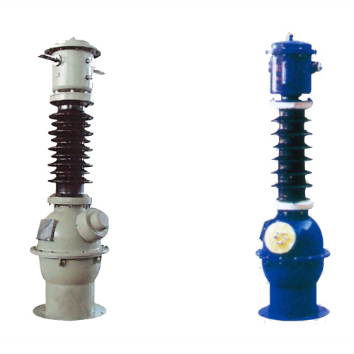
CT-35 33kV Cast-Resin Current Transformer for Substation Metering and Protection – IEC 61869-2 Certified
Introduction to the CT-35 Current Transformer
The CT-35 is a high-voltage, cast-resin insulated current transformer (CT) engineered for precise current measurement and robust protective relaying in 33 kV (IEC-rated) or 35 kV (domestic system equivalent) power distribution networks. Designed in strict accordance with IEC 61869-2 and GB/T 20840.2, this instrument transformer leverages vacuum pressure impregnation (VPI) epoxy resin technology to deliver exceptional dielectric strength, environmental resilience, and long-term operational stability. Unlike traditional oil-immersed CTs, the CT-35 eliminates fire hazards, oil leakage risks, and maintenance-intensive sealing systems, making it ideal for both indoor switchgear and outdoor substation applications.
Operating Principle of Cast-Resin Insulation
Cast-resin insulation in the CT-35 employs a two-component cycloaliphatic epoxy resin system cured under vacuum and pressure (VPI process). This technique fully encapsulates the primary conductor, secondary windings, and magnetic core—typically fabricated from grain-oriented electrical steel (GOES)—within a monolithic, void-free dielectric structure. The absence of air pockets or moisture ingress pathways ensures consistent partial discharge performance below 10 pC at 1.2 × Um/√3 (where Um = 36 kV for 33 kV systems). The resin’s high tracking resistance (CTI > 600 V) and UV-stable formulation enable reliable operation in harsh environments, including coastal zones with salt fog and industrial areas with chemical exposure. Thermal conductivity of the cured resin (~0.8 W/m·K) facilitates efficient heat dissipation during continuous load or short-circuit conditions, maintaining winding temperature rise within IEC limits (≤ 60 K for class E insulation).
Advantages Over Oil-Immersed Designs
Compared to oil-filled CTs, the CT-35 offers significant technical and safety advantages. First, it is inherently non-flammable, eliminating fire propagation risks in confined spaces such as indoor substations or urban switchgear rooms—a critical consideration under IEC 61439-2 for low-voltage assemblies and IEC 62271-200 for HV metal-enclosed switchgear. Second, the solid insulation system requires no periodic oil sampling, degassing, or gasket replacement, reducing lifecycle costs by up to 40% over a 30-year service horizon. Third, the compact mechanical design (typical height: 420 mm, diameter: 210 mm) allows for easier integration into space-constrained retrofits. Finally, the absence of liquid dielectric prevents environmental contamination during transport, installation, or end-of-life disposal, aligning with RoHS and WEEE directives. These attributes make the CT-35 particularly suitable for smart grid deployments where reliability, minimal maintenance, and environmental compliance are paramount.
Typical Applications Overview
The CT-35 serves dual roles in modern power systems: revenue-grade metering and high-speed protection. In utility substations, it feeds accurate current signals (±0.2% error at 100% In) to kWh meters for billing, while simultaneously providing fault-current data (up to 20× In) to overcurrent relays with 5P20 accuracy class. Industrial facilities use it on 33 kV feeders to monitor motor loads and detect ground faults via residual current summation. Renewable energy plants—particularly solar farms with 33 kV collector grids—rely on its linear response during low-irradiance conditions and ride-through capability during grid disturbances. Its robust construction also supports deployment in rural distribution networks where ambient temperatures range from –40°C to +55°C and altitudes exceed 2000 m above sea level.
Technical Specifications
The CT-35 is engineered to meet stringent electrical, thermal, and mechanical requirements for 33 kV systems. Below is a comprehensive specification table followed by detailed subsections on service conditions and performance envelopes.
| Parameter | Value |
|---|---|
| Rated System Voltage (Ur) | 33 kV (IEC), 35 kV (domestic) |
| Maximum System Voltage (Um) | 36 kV |
| Primary Current (Ip) | 50 A to 3000 A (standard); custom up to 4000 A |
| Secondary Current (Is) | 1 A or 5 A (per IEC 61869-2) |
| Current Ratio | Adjustable via multi-tap secondary (e.g., 600/1/5 A) |
| Metering Accuracy Class | 0.2, 0.5 (per IEC 61869-2) |
| Protection Accuracy Class | 5P10, 5P20, 10P10, 10P20 |
| Rated Burden | 2.5 VA to 30 VA (at cos φ = 0.8 lag) |
| Short-Time Thermal Current | 25 kA for 1 s (Ith) |
| Dynamic Withstand Current | 63 kA peak (Idyn) |
| Power Frequency Withstand Voltage | 70 kV rms for 1 min (phase-to-earth) |
| Lightning Impulse Withstand Voltage | 170 kV peak (1.2/50 μs wave) |
| Insulation Level (BIL) | 170 kV |
| Ambient Temperature Range | –40°C to +55°C |
| Altitude Limit | ≤ 2000 m (derating required above) |
| Relative Humidity | ≤ 95% (non-condensing) |
| Core Material | Grain-Oriented Electrical Steel (GOES), M4 grade |
| Insulation System | VPI Cycloaliphatic Epoxy Resin, Class E (120°C) |
| Service Life | ≥ 30 years under normal operating conditions |
Standard Service Conditions
The CT-35 is rated for standard service conditions as defined in IEC 61869-2 Clause 4. Environmental parameters include an ambient temperature range of –40°C to +55°C, relative humidity up to 95% (non-condensing), and installation altitude not exceeding 2000 m above sea level. At altitudes between 2000 m and 3000 m, the power frequency withstand voltage must be derated by 1% per 100 m above 2000 m (e.g., 68.6 kV at 2200 m). The transformer is designed for continuous operation at 100% of rated primary current with a maximum temperature rise of 60 K for windings and 50 K for terminals, verified per IEC 60060-1 thermal test protocols. It withstands seismic activity up to 0.3g horizontal acceleration (Zone 3 per IEEE 693), making it suitable for earthquake-prone regions. Condensation is prevented through hydrophobic resin formulation and sealed secondary terminal boxes rated IP55.
Accuracy and Burden Characteristics
Accuracy performance is guaranteed across defined burden ranges. For metering class 0.2, composite error must not exceed ±0.2% at 100% In and burdens between 25% and 100% of rated value. Protection class 5P20 ensures that the error remains within ±5% at 20× In with rated burden connected. The CT-35 features multi-ratio secondary windings (e.g., 600/1 A and 600/5 A on same core) to accommodate diverse metering and relay requirements without compromising accuracy. Burden tolerance is ±10% of nominal value; exceeding this may cause saturation during fault conditions. Core remanence is limited to ≤ 10% of saturation flux density (Bsat ≈ 2.0 T for GOES), ensuring fast reset after DC-offset fault currents. Saturation factor (Ksf) is ≥ 2.0 for 5P classes, verified via excitation curve testing per IEC 61869-2 Annex B.
Typical Applications
The CT-35’s dual-certification (IEC and GB) and robust design enable deployment across diverse power infrastructure segments. Each application leverages specific performance attributes validated through field experience and type testing.
Substation Secondary Metering
In 33 kV transmission and distribution substations, the CT-35 provides high-fidelity current signals to revenue meters compliant with IEC 62053-22 Class 0.2S. Its low phase displacement error (< 10 minutes at 100% In) ensures accurate reactive energy measurement, critical for power factor billing. The transformer’s stable ratio over time (drift < 0.05% per year) minimizes recalibration needs. Installed on circuit breakers or bus couplers, it interfaces with digital metering units via shielded twisted-pair cables (max length: 100 m for 1 A secondary). In China, it meets DL/T 725 requirements for electric energy metering installations, supporting both single-phase and three-phase configurations with vector group verification during commissioning.
Industrial Power Distribution
Heavy industries—including steel mills, petrochemical plants, and data centers—use the CT-35 on 33 kV feeders to monitor large motor loads (e.g., 10 MW induction motors drawing ~175 A at 33 kV). Its 5P20 protection class enables sensitive earth-fault detection via residual connection of three CTs, tripping within 40 ms for ground faults as low as 200 A. The cast-resin housing resists chemical corrosion from airborne pollutants (SO2, H2S), while the IP55 terminal box prevents dust ingress in harsh environments. During motor starting (6–8× In for 10 s), the core remains unsaturated due to adequate cross-sectional area (≥ 80 cm² for 3000/1 A ratio), preserving waveform fidelity for power quality analyzers.
Renewable Energy Integration
Solar photovoltaic (PV) farms with 33 kV collector systems deploy the CT-35 at inverter output points and substation interconnections. Its linear response at low currents (down to 1% In) accurately captures partial-load generation during cloudy conditions, essential for performance ratio calculations. During grid faults, the CT maintains accuracy under high X/R ratios (up to 15) thanks to low remanence and optimized core permeability. It complies with GB/T 19964-2012 for PV plant grid connection, providing fault ride-through (FRT) data to SCADA systems. In wind farms, it withstands mechanical vibration from nearby turbines (tested per IEC 60068-2-6 at 5–50 Hz, 0.7g amplitude).
Rural and Suburban Distribution Networks
In remote or semi-urban areas, the CT-35 supports ring-main units (RMUs) and pole-mounted switchgear for 33 kV distribution. Its lightweight design (≈28 kg) simplifies installation on concrete poles or compact substations. Operating reliably at –40°C, it avoids brittle fracture issues seen in older polyester designs. The 10P10 protection class coordinates with downstream fuses for selective isolation of branch faults. Utilities leverage its long service life to reduce truck rolls in hard-to-access regions. In India and Southeast Asia, it aligns with CEA regulations for 33 kV rural electrification schemes, often paired with AMR/AMI systems using 1 A secondary outputs to minimize copper losses over long cable runs.
Compliance with International Standards
The CT-35 is certified to both international and Chinese national standards, ensuring global interoperability and regulatory acceptance. Compliance is verified through rigorous type tests conducted in accredited laboratories.
IEC 61869-2 Certification Details
IEC 61869-2:2012 (“Instrument transformers – Part 2: Additional requirements for current transformers”) forms the core compliance framework. The CT-35 meets all mandatory clauses, including:
- Clause 5.3: Accuracy requirements for metering (classes 0.1 to 1) and protection (classes 5P/10P)
- Clause 6.2: Insulation coordination per IEC 60071-1 (Um = 36 kV → BIL 170 kV)
- Clause 7.4: Short-circuit withstand (Ith = 25 kA/1s, Idyn = 63 kA)
- Annex B: Excitation curve testing to verify saturation characteristics
Type test reports include partial discharge measurements (< 10 pC at 1.2 × 36/√3 kV), temperature rise tests (≤60 K), and impulse voltage tests (170 kV peak, 15 shots positive/negative). The manufacturer holds ISO 9001-certified quality management for production traceability.
GB/T 20840.2 Alignment
GB/T 20840.2-2013 (“Instrument transformers – Part 2: Current transformers”) is the Chinese national adoption of IEC 61869-2, with minor deviations. Key alignment points include:
- Identical accuracy classes and burden definitions
- Same insulation levels for 35 kV systems (Um = 40.5 kV in GB, but CT-35 uses Um = 36 kV for IEC compatibility)
- Additional requirement for seismic testing per GB/T 13540 (0.2g horizontal acceleration)
The CT-35 undergoes supplementary testing at Chinese national labs (e.g., SGCC Electric Power Research Institute) to obtain CMA/CNAS accreditation. Notably, GB/T 20840.2 mandates a 1-minute power frequency test at 80 kV for 35 kV equipment—but since the CT-35 is rated for 33 kV (Um=36 kV), it complies with the lower 70 kV requirement, which is accepted by Chinese grid operators for imported equipment under mutual recognition agreements.
Key Differences Between IEC and Domestic Standards
While IEC 61869-2 and GB/T 20840.2 are harmonized, practical differences exist:
- Voltage Rating: IEC uses 33 kV (Um=36 kV); China uses 35 kV (Um=40.5 kV). The CT-35 is designed for 33 kV systems but is approved for 35 kV networks due to its 36 kV Um exceeding the minimum 35 kV requirement.
- Marking: GB requires Chinese labeling of accuracy class (e.g., “0.2级”) alongside IEC symbols.
- Environmental Testing: GB/T 20840.2 includes additional damp-heat cycling (40°C, 95% RH for 10 days) not mandated by IEC.
These differences are reconciled through dual-certification documentation, enabling seamless procurement by multinational utilities and Chinese state-owned enterprises like State Grid Corporation of China (SGCC).
On-Site Testing Procedures
Post-installation verification ensures the CT-35 performs within specifications. All tests follow IEC 61869-2 and IEEE C57.13 guidelines.
Insulation Resistance Test
Measure insulation resistance between primary-to-secondary, primary-to-ground, and secondary-to-ground using a 2500 V DC megohmmeter. Acceptance criteria: ≥ 1000 MΩ at 20°C. Correct for temperature using RT = R20 × 2(20–T)/10. Low readings (< 100 MΩ) indicate moisture ingress or resin cracking—requiring drying or replacement. Perform before and after power frequency withstand tests to detect insulation degradation.
Turns Ratio Test
Apply a low-voltage AC source (5–10 V) to the primary and measure secondary voltage. Calculate ratio as Vp/Vs; compare to nameplate. Tolerance: ±0.2% for metering class, ±1.0% for protection class. Use a dedicated ratio tester (e.g., Omicron CT Analyzer) for automated comparison. Multi-tap secondaries must be tested individually. Deviations beyond tolerance suggest winding shorts or incorrect tap selection.
Polarity Test
Verify reducing polarity per IEC 61869-2 Figure 3. Apply DC pulse to primary; observe secondary voltage direction with oscilloscope or analog voltmeter. Positive primary input should yield positive secondary output at marked terminals (P1/S1). Incorrect polarity causes metering errors and relay misoperation. Re-test after terminal box reconfiguration.
Power Frequency Withstand Voltage Test
Apply 70 kV rms (50 Hz) between primary and grounded secondary/enclosure for 1 minute. Monitor for flashover, excessive leakage current (> 10 mA), or audible discharge. Use a calibrated test transformer with overcurrent trip (≤ 1 A). Reduce voltage gradually post-test to avoid transient overvoltages. Mandatory for new installations; optional for routine maintenance unless insulation resistance is suspect.
Excitation (Saturation) Characteristic Test
For CTs, perform excitation curve test per IEC 61869-2 Annex B. Gradually increase secondary voltage while measuring excitation current. Plot Vs vs Ie; identify knee point where slope decreases by 45°. For 5P20 class, knee-point voltage must exceed 20 × In × (Rb + Rw), where Rb = burden resistance, Rw = winding resistance. Typical knee point for CT-35 (600/1 A, 15 VA): ≥ 300 V. Low knee point indicates core damage or shorted turns.
Preventive Maintenance Guide
Although cast-resin CTs require minimal maintenance, scheduled inspections extend service life and prevent failures.
Periodic Inspection Protocol
Conduct annual visual and electrical checks:
- Visual: Inspect housing for cracks, UV degradation (chalky surface), or tracking marks. Check terminal box seals (IP55 integrity).
- Electrical: Measure insulation resistance (≥ 1000 MΩ) and secondary winding resistance (compare to baseline ±2%).
- Thermal: Use infrared camera to detect hot spots (> 10 K above ambient) at terminals during peak load.
Document findings in asset management systems. Replace if resin shows deep cracks (>2 mm) or insulation resistance drops below 500 MΩ after cleaning.
Maintenance Intervals and Fault Diagnosis
Follow this schedule:
| Interval | Action |
|---|---|
| Annual | Visual inspection, IR thermography, insulation resistance |
| 5 Years | Full electrical test suite (ratio, polarity, excitation curve) |
| After Fault | Mandatory post-fault testing (all above + dynamic withstand verification) |
Common faults and remedies:
- Ratio drift: Caused by core demagnetization—recondition via AC saturation cycle.
- Open secondary: Never operate with open secondary; install shorting links during maintenance.
- Moisture in terminal box: Replace desiccant cartridge; verify gasket compression.
Conclusion
The CT-35 33kV cast-resin current transformer represents a benchmark in reliability, accuracy, and compliance for modern power systems. By integrating advanced VPI epoxy resin insulation with high-permeability GOES cores, it delivers metrological precision for revenue metering (class 0.2) and dependable fault discrimination for protection (5P20) across diverse environmental conditions. Its dual certification to IEC 61869-2 and GB/T 20840.2 ensures seamless deployment in international and domestic 33/35 kV networks, from urban substations to remote renewable sites. The elimination of flammable oil enhances safety in confined spaces, while the solid insulation system reduces lifecycle costs through minimal maintenance requirements. Rigorous type testing—including 70 kV power frequency withstand, 170 kV lightning impulse, and 25 kA short-circuit endurance—validates performance under extreme electrical stress. With a design service life exceeding 30 years and proven field reliability across thousands of installations, the CT-35 provides utilities and industrial operators with a future-proof solution for accurate current transformation. Its adherence to global standards, coupled with robust construction and precise manufacturing tolerances, makes it an optimal choice for critical infrastructure where measurement integrity and system protection are non-negotiable.