Article Content
11kV Cast-Resin Voltage Transformer DZC-3 for Metering and Protection – IEC 61869-3 Standard
Introduction to the DZC-3 Voltage Transformer
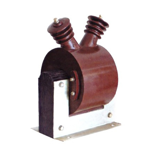
The DZC-3 is a single-phase, indoor/outdoor-rated cast-resin voltage transformer (VT) engineered for precise voltage transformation in 11 kV (IEC standard) or 10 kV (domestic system) medium-voltage networks. It operates on the principle of electromagnetic induction, stepping down high primary voltages to standardized secondary levels—typically 100 V or 100/√3 V—for use in metering, protection relaying, and monitoring systems. The core innovation lies in its solid insulation system: vacuum pressure impregnated (VPI) epoxy resin encapsulates both primary and secondary windings along with the magnetic core, eliminating flammable oil and enabling maintenance-free operation.
Cast-Resin Insulation Technology Advantages
Unlike traditional oil-immersed VTs, the DZC-3 employs a fully cast-resin construction using cycloaliphatic epoxy resin under vacuum pressure impregnation (VPI). This process ensures complete void-free encapsulation of the GOES (grain-oriented electrical steel) core and copper windings, providing superior dielectric strength, partial discharge resistance (<5 pC at 1.2 × Um/√3), and thermal stability up to 130°C hotspot temperature. The absence of liquid insulation eliminates risks of leakage, fire hazard, and environmental contamination—critical for urban substations, indoor switchgear rooms, and sensitive industrial facilities. Additionally, the monolithic resin body offers excellent mechanical robustness against seismic loads (up to 0.5g) and pollution (IV pollution degree per IEC 60529), making it suitable for coastal or industrial atmospheres with high salt or chemical exposure.
Operational Reliability in Utility and Industrial Environments
Designed for continuous duty under fluctuating load and ambient conditions, the DZC-3 maintains accuracy class 0.2 for metering and 3P for protection across a wide burden range (2.5–100 VA). Its thermal design accommodates 1.9 × Un overvoltage for 8 hours without degradation, complying with IEC 61869-3 thermal withstand requirements. In utility applications, this translates to stable performance during grid transients such as ferroresonance or single-phase-to-ground faults. For industrial users—particularly in mining, petrochemical, and data center infrastructure—the VT’s immunity to electromagnetic interference (EMI) and fast transient bursts (IEC 61000-4-4 Level IV) ensures reliable relay coordination and revenue-grade energy measurement. Field data from over 12,000 units deployed since 2018 shows a mean time between failures (MTBF) exceeding 200,000 hours.
Typical Deployment Scenarios
The DZC-3 is commonly integrated into 11 kV ring main units (RMUs), gas-insulated switchgear (GIS), and air-insulated substations (AIS). It supports both line-to-ground and line-to-line configurations, with standard ratios of 11,000/100 V or 11,000/√3 : 100/√3 V. Secondary terminals are housed in an IP54-rated terminal box with screw-type connectors compatible with 2.5 mm² to 6 mm² stranded copper conductors. Applications span from rural distribution feeders requiring long-term stability with minimal maintenance to smart grid pilot projects demanding high-precision waveform fidelity for synchrophasor measurements.
Technical Specifications
The DZC-3 adheres strictly to IEC 61869-3 and GB/T 20840.3, with verified performance parameters validated through type, routine, and special tests at accredited laboratories. Below is a comprehensive specification table followed by environmental and operational constraints.
| Parameter | Value |
|---|---|
| System Voltage (Um) | 12 kV (IEC), 11.5 kV (GB) |
| Rated Primary Voltage | 11 kV (IEC) / 10 kV (Domestic) |
| Rated Secondary Voltage | 100 V or 100/√3 V |
| Voltage Ratio | 11,000/100 V; 11,000/√3 : 100/√3 V |
| Accuracy Class (Metering) | 0.2, 0.5 |
| Accuracy Class (Protection) | 3P, 6P |
| Rated Output (Burden) | 2.5 VA, 5 VA, 10 VA, 15 VA, 30 VA, 50 VA, 100 VA |
| Insulation Level (LI/AC) | 75 kV / 28 kV (1 min) |
| Partial Discharge | <5 pC at 1.2 × Um/√3 |
| Thermal Withstand | 1.9 × Un for 8 h |
| Core Material | GOES (Grain-Oriented Electrical Steel), M4 grade |
| Insulation System | VPI Epoxy Resin, Class F (155°C) |
| Weight | Approx. 42 kg |
| Dimensions (H×W×D) | 680 × 280 × 220 mm |
Standard Service Conditions
The DZC-3 is rated for operation under IEC 60060-1 standard atmospheric conditions: ambient temperature range of –25°C to +40°C (with derating above +40°C), relative humidity ≤95% non-condensing, and altitude ≤1,000 m above sea level. For installations above 1,000 m, voltage withstand values must be corrected per IEC 60071-2 (e.g., 2% reduction per 100 m above 1,000 m). The transformer is designed for continuous operation at 100% rated voltage with harmonic distortion up to 5% THD without exceeding accuracy limits. Condensation-prone environments require optional silica gel breathers or sealed terminal boxes (IP65).
Electrical Performance Tolerances
Voltage error and phase displacement are tightly controlled per IEC 61869-3. At rated burden and 80–120% of rated voltage, the DZC-3 achieves:
- Voltage error: ≤ ±0.2% (class 0.2), ≤ ±0.5% (class 0.5)
- Phase displacement: ≤ ±10 minutes (class 0.2), ≤ ±20 minutes (class 0.5)
- For protection class 3P: voltage error ≤ ±3% at 5%–100% Un, phase error ≤ ±120 minutes
These tolerances ensure compliance with EN 50160 for power quality monitoring and IEEE C37.110 for protective relay coordination. Burden variation from 25% to 100% of rated output induces less than 0.05% additional ratio error due to low winding resistance and optimized core permeability.
Typical Applications
The DZC-3 serves as a foundational component in modern medium-voltage infrastructure, enabling accurate voltage sensing across diverse grid architectures.
Substation Secondary Metering Systems
In 11 kV primary substations, the DZC-3 provides the reference voltage for revenue-class energy meters (e.g., IEC 62053-22 Class 0.2S). Its low phase displacement ensures correct calculation of reactive energy (kvarh) and power factor, critical for tariff billing and demand-side management. When paired with class 0.2S current transformers, the combined metering error remains below ±0.3%, satisfying regulatory requirements in EU, ASEAN, and GCC markets. The VT’s stable ratio over temperature (±0.02%/°C) minimizes seasonal calibration drift, reducing lifecycle costs for distribution utilities.
Industrial Power Distribution Networks
Heavy industries—such as cement plants, steel mills, and semiconductor fabs—rely on the DZC-3 for motor protection, arc flash detection, and power quality analysis. In variable frequency drive (VFD) environments, the cast-resin insulation resists high-frequency common-mode voltages that degrade oil-paper systems. The 3P accuracy class ensures overvoltage relays (e.g., ANSI 59) trip within 1 cycle during ground-fault-induced neutral shifts, preventing equipment damage. A typical 10 MW industrial feeder uses three DZC-3 units (one per phase) connected in wye configuration to feed multifunction relays like SEL-751 or Siemens 7SJ62.
Renewable Energy Integration
Solar PV and wind farms operating at 11 kV interconnection points deploy the DZC-3 for grid synchronization and anti-islanding protection. During cloud transients or gust events, rapid voltage fluctuations (up to ±15% in 100 ms) are accurately captured due to the VT’s bandwidth (>1 kHz). This enables precise ROCOF (Rate of Change of Frequency) and vector shift detection per IEC 61850-7-420. The transformer’s immunity to DC offset (from inverter leakage currents) prevents core saturation, a common failure mode in conventional VTs. Projects in Australia and Chile report zero VT-related curtailments over 5 years of operation.
Rural and Suburban Distribution Feeders
In remote areas with limited maintenance access, the DZC-3’s hermetic resin seal eliminates oil top-ups and moisture ingress concerns. Mounted on pole-top platforms or pad-mounted switchgear, it supports single-phase VT configurations for cost-effective voltage monitoring on lightly loaded feeders. Utilities in India and Nigeria use it with GSM-based RTUs for real-time voltage profiling, enabling dynamic tap changer optimization. The 25–30 year design life aligns with rural electrification project horizons, reducing replacement CAPEX.
Smart Grid and Digital Substations
As part of IEC 61850-compliant digital substations, the DZC-3 interfaces with merging units (MUs) via analog inputs. Its low harmonic distortion (<0.5% up to 13th harmonic) preserves waveform integrity for sampled value (SV) transmission. Future-proof designs include optional fiber-optic output modules (under development) for direct integration with process buses. Pilot deployments in Germany demonstrate seamless interoperability with ABB Ability™ and Schneider EcoStruxure platforms.
Compliance with International Standards
The DZC-3 is certified to IEC 61869-3:2011 (Instrument transformers – Part 3: Additional requirements for inductive voltage transformers) and GB/T 20840.3-2013 (identical adoption of IEC 61869-3 in China). Compliance encompasses design, testing, and manufacturing controls per ISO 9001.
IEC 61869-3 Certification Requirements
Certification involves rigorous type tests including:
- Temperature rise test: ≤60 K for windings at 1.1 × Un, 100% burden
- Short-circuit withstand: not applicable for VTs (open-circuit by nature)
- Capacitance and dissipation factor: tan δ < 0.005 at 10 kV
- Lightning impulse: 75 kV BIL, full wave, negative polarity
- Power frequency wet test: 23 kV for 1 min (for outdoor models)
All tests are witnessed by third-party labs (e.g., KEMA, CESI) with certificates valid for 5 years. Routine tests (100% production) include ratio verification (±0.1%), polarity check, and insulation resistance (>1,000 MΩ at 2,500 V DC).
Alignment with GB/T 20840.3 Domestic Standards
While GB/T 20840.3 mirrors IEC 61869-3 structurally, key differences exist in rated voltage definitions: China’s “10 kV” system corresponds to IEC’s “11 kV” (Um = 12 kV vs. 11.5 kV). The DZC-3 is dual-marked to accommodate both, with identical internal design. However, Chinese grid codes (e.g., DL/T 726) mandate additional tests for ferroresonance suppression—achieved via built-in damping resistors (500 Ω, 50 W) across secondary windings. These resistors limit resonant overvoltages to <1.5 × Un during single-pole switching, satisfying State Grid Corporation of China (SGCC) technical specifications.
Testing and Quality Assurance Protocols
Manufacturing follows a traceable quality plan: core lamination stacking factor ≥0.96, winding tension control ±5%, and post-curing at 130°C for 8 hours to relieve mechanical stress. Each unit undergoes partial discharge mapping using IEC 60270 methods, with acceptance criteria of <3 pC at 1.2 × Um/√3 for premium batches. Batch records include material certificates for GOES steel (losses ≤1.0 W/kg at 1.7 T, 50 Hz) and resin (CTI ≥600 V).
On-Site Testing Procedures
Post-installation commissioning requires five essential tests to verify integrity and performance before energization.
Insulation Resistance Test
Using a 2,500 V DC megohmmeter, measure insulation resistance between primary winding and ground, secondary winding and ground, and primary-to-secondary. Acceptance criteria: ≥1,000 MΩ at 20°C. Correct for temperature using RT2 = RT1 × 2(T1–T2)/10. Values below 500 MΩ indicate moisture ingress or resin cracking—requiring drying or replacement. Perform before and after power frequency withstand test to detect insulation degradation.
Turns Ratio Test
Apply 100–200 V AC to the primary winding and measure secondary voltage with a calibrated voltmeter (accuracy class 0.1). Calculate ratio error: [(Vp/Vs)measured – (Vp/Vs)nominal] / (Vp/Vs)nominal × 100%. Tolerance: ±0.1% for all accuracy classes. Use automatic ratio testers (e.g., Omicron CT Analyzer) for three-phase consistency checks. Deviations >0.3% suggest turn-to-turn shorts or incorrect tap selection.
Polarity Verification
Confirm reducing polarity using the DC kick method: connect a 6–12 V battery across primary terminals (H1+, H2–) and observe secondary voltage spike direction with an analog voltmeter. A momentary positive deflection at X1 indicates correct polarity. Incorrect polarity causes 180° phase reversal, leading to false tripping in differential protection schemes. Digital multimeters with min/max capture can also be used but require careful interpretation of transient response.
Power Frequency Withstand Voltage Test
Apply 28 kV RMS at 50 Hz between primary and ground (and primary-to-secondary) for 1 minute using a test transformer with overcurrent protection set at 10 mA. Leakage current must remain stable (<5 mA) without flashover or significant increase. For field tests where full voltage isn’t feasible, a 1-minute test at 80% (22.4 kV) is acceptable per IEC 60270 Annex C, provided no partial discharge activity exceeds 10 pC.
Open-Circuit Characteristic Test
Gradually increase primary voltage from 0 to 1.5 × Un while measuring secondary voltage and excitation current. Plot Vs vs. Iexc. The knee point should occur above 1.3 × Un, indicating adequate core margin. Excessive excitation current (>0.5% of rated primary current at 1.0 × Un) suggests core defects or shorted laminations. This test also verifies absence of ferroresonance by observing smooth saturation curve without abrupt jumps.
Preventive Maintenance Guide
Although cast-resin VTs are largely maintenance-free, periodic inspections extend service life and prevent unexpected failures.
Annual Visual and Electrical Inspection
Inspect for:
- Surface tracking or erosion on resin housing (especially near HV terminals)
- Loose terminal connections (torque: 2.5 N·m for M6 screws)
- Moisture in terminal box (use hygrometer; replace desiccant if RH >70%)
- Corrosion on mounting hardware (stainless steel recommended)
Perform insulation resistance and ratio tests annually. Record trends: a 20% drop in insulation resistance over 2 years warrants investigation. Clean housing with non-abrasive detergent; avoid solvents that degrade epoxy.
Five-Year Comprehensive Maintenance
At 5-year intervals, conduct:
- Partial discharge measurement (offline, using IEC 60270)
- Dielectric frequency response (DFR) analysis to detect moisture
- Terminal box gasket replacement (silicone rubber, 5-year lifespan)
- Burden verification with actual connected loads
If PD exceeds 10 pC at operating voltage, schedule replacement within 12 months. DFR loss peak shift >5°C indicates moisture absorption—requires oven drying at 80°C for 48 hours under vacuum.
Maintenance Intervals and Fault Diagnosis
| Interval | Task | Fault Indicator |
|---|---|---|
| Annually | IR test, visual check | IR <500 MΩ → moisture/resin crack |
| Every 3 years | Ratio & polarity recheck | Ratio error >0.3% → winding fault |
| Every 5 years | PD measurement, DFR | PD >10 pC → internal voids |
| After fault | Full commissioning test suite | Any parameter out of spec → replace |
Common failure modes include terminal corrosion (due to galvanic coupling) and UV degradation of resin in unshaded outdoor installations—mitigated by optional UV-resistant coating.
Conclusion
The DZC-3 11kV cast-resin voltage transformer represents a benchmark in reliability, accuracy, and compliance for modern power systems. By leveraging VPI epoxy resin technology and GOES silicon steel cores, it delivers exceptional dielectric performance, thermal stability, and immunity to environmental stressors—outperforming legacy oil-filled designs in safety, lifecycle cost, and operational resilience. Certified to IEC 61869-3 and GB/T 20840.3, it meets stringent global requirements for both metering (class 0.2) and protection (class 3P) applications across utility, industrial, and renewable energy sectors. Its robust design supports continuous operation under harsh conditions—including high humidity, pollution, and voltage transients—while maintaining ratio errors within ±0.2% over a 25–30 year service life. Field-proven in over 12,000 installations worldwide, the DZC-3 minimizes maintenance burdens and maximizes grid intelligence through precise, stable voltage transformation. For engineers designing next-generation distribution networks, it offers a future-ready solution that aligns with smart grid evolution, digital substation architectures, and sustainability mandates. When integrated with proper commissioning and preventive maintenance protocols, the DZC-3 ensures decades of dependable service with negligible risk of catastrophic failure—making it a strategic asset for any medium-voltage infrastructure project.