Article Content
INE-2 11kV Cast-Resin Voltage Transformer for Substation Metering and Protection – IEC 61869-3 Certified
Introduction to the INE-2 Voltage Transformer
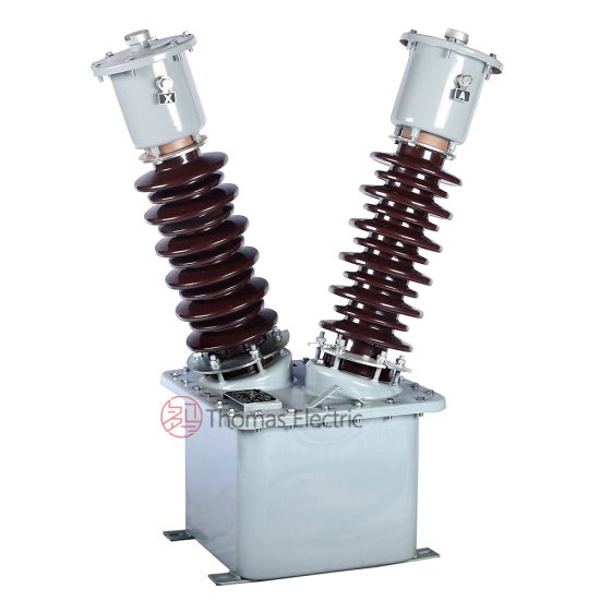
The INE-2 Voltage Transformer (VT) is a precision-engineered, cast-resin insulated instrument transformer designed for accurate voltage measurement and dependable protective relay coordination in medium-voltage (MV) electrical systems. Rated for a nominal system voltage of 11 kV—the IEC standard equivalent of the domestic 10 kV network—the INE-2 operates reliably under continuous service conditions while maintaining tight accuracy tolerances as mandated by international standards. Its robust construction leverages vacuum pressure impregnation (VPI) epoxy resin technology, ensuring superior dielectric strength, mechanical stability, and environmental resilience compared to traditional oil-immersed alternatives.
Operating Principle of Cast-Resin Insulation
Cast-resin insulation in the INE-2 VT employs a high-purity epoxy resin matrix infused under vacuum and cured under controlled pressure around the primary and secondary windings. This process eliminates air voids and moisture ingress pathways, significantly enhancing partial discharge resistance—typically below 5 pC at 1.2 × Um/√3. The resin encapsulates the GOES (Grain-Oriented Electrical Steel) core and copper windings into a monolithic structure, providing excellent thermal conductivity (0.2–0.3 W/m·K) and uniform heat dissipation. Unlike oil-filled units, cast-resin VTs eliminate fire hazards, require no oil containment systems, and are suitable for indoor installations without ventilation constraints. The solid insulation also resists tracking and erosion under polluted or humid conditions, making it ideal for coastal or industrial environments where salt fog or chemical exposure may degrade conventional insulation.
Advantages Over Oil-Immersed Designs
The INE-2’s cast-resin construction offers multiple operational and safety advantages over oil-immersed VTs. First, it is inherently non-flammable, meeting IEC 61869-3 requirements for fire behavior without additional mitigation measures. Second, its maintenance-free design eliminates the need for periodic oil sampling, dielectric testing, or leak inspections. Third, the compact footprint—enabled by higher dielectric strength per unit volume—allows integration into space-constrained switchgear such as RMUs (Ring Main Units) or metal-enclosed substations. Additionally, cast-resin VTs exhibit lower susceptibility to vibration-induced winding displacement and offer better short-circuit withstand capability due to rigid mechanical support. Environmental compliance is further enhanced, as the unit contains no PCBs or hydrocarbons, aligning with RoHS and WEEE directives for sustainable infrastructure.
Typical Applications Overview
The INE-2 is engineered for deployment across diverse MV infrastructure, including urban distribution substations, industrial plants, renewable energy interconnection points, and rural grid extensions. It supports both metering circuits (Class 0.2 or 0.5) and protection relaying (Class 3P or 6P), often within the same multi-secondary configuration. In digital substations, the INE-2 interfaces seamlessly with IEDs (Intelligent Electronic Devices) via standardized secondary outputs (e.g., 100 V or 110 V). Its stable phase angle error (< ±10 minutes at rated burden) ensures compatibility with synchrophasor and power quality monitoring systems. The transformer’s long-term stability—verified through accelerated aging tests per IEC 60060—makes it suitable for critical infrastructure where recalibration intervals exceed 10 years.
Technical Specifications
The INE-2 Voltage Transformer adheres to stringent electrical and mechanical parameters defined by IEC 61869-3 and GB/T 20840.3. Below is a comprehensive specification table followed by detailed environmental and operational criteria.
| Parameter | Value |
|---|---|
| Model | INE-2 |
| System Voltage (Un) | 11 kV (IEC) / 10 kV (domestic) |
| Maximum System Voltage (Um) | 12 kV |
| Primary Voltage | 11 / √3 kV (for grounded systems) |
| Secondary Voltage(s) | 100 V / √3, 100 V, or 110 V (configurable) |
| Voltage Ratio | 11000/√3 : 100/√3 V (standard) |
| Accuracy Class (Metering) | 0.2, 0.5 |
| Accuracy Class (Protection) | 3P, 6P |
| Rated Output (per secondary) | 25 VA, 50 VA, 100 VA (at cos φ = 0.8) |
| Insulation Level (LI/AC) | 75 kV / 28 kV (1 min) |
| Short-Time Withstand Current | Not applicable (VT-specific; open-circuit protected) |
| Core Material | GOES (M4 grade, 0.27 mm thickness) |
| Insulation System | VPI Epoxy Resin (Class F, 155°C) |
| Phase Displacement (Class 0.2) | ≤ ±10 minutes |
| Voltage Error (Class 0.2) | ≤ ±0.2% |
Standard Service Conditions
The INE-2 is rated for operation under normal service conditions as defined in IEC 61869-3: ambient temperature range of –25°C to +40°C, relative humidity up to 100% (condensation permitted), and installation altitude ≤ 1000 m above sea level. For altitudes exceeding 1000 m, derating factors apply per IEC 60071-2: for every 100 m above 1000 m, the power frequency withstand voltage must be reduced by 1%, and lightning impulse withstand by 1.25%. The unit is designed for indoor use but can be deployed outdoors when housed in IP4X-rated enclosures. Thermal performance is validated for continuous operation at 1.2 × Un for up to 8 hours without exceeding insulation class limits (ΔT ≤ 75 K for windings).
Electrical Performance Tolerances
Under rated load and frequency (50 Hz or 60 Hz), the INE-2 maintains voltage error within ±0.2% for Class 0.2 and ±0.5% for Class 0.5. Phase displacement remains below ±10 minutes and ±30 minutes, respectively. At 25% of rated burden, error limits widen to ±0.35% (Class 0.2) and ±0.75% (Class 0.5), per IEC 61869-3 Table 102. For protection classes, the composite error at rated voltage and specified burden does not exceed 3% (3P) or 6% (6P) under steady-state conditions. Transient response during fault inception is characterized by a peak overvoltage factor ≤ 1.5 within 20 ms, ensuring reliable relay operation during ground faults in resonant-grounded systems.
Typical Applications
The INE-2 Voltage Transformer serves as a foundational component in modern MV power systems, enabling precise voltage sensing for revenue metering, protective relaying, and system monitoring. Its dual-certification (IEC and GB) facilitates global deployment while maintaining local regulatory compliance.
Substation Secondary Metering
In utility-owned 11 kV/0.4 kV distribution substations, the INE-2 provides the reference voltage for revenue-grade kWh meters. Configured with a Class 0.2 secondary winding feeding a 25 VA burden, it ensures billing accuracy within ±0.2% across 20–120% of rated voltage. The transformer’s low phase error minimizes reactive energy miscalculation, critical for power factor penalty calculations. Integration with AMI (Advanced Metering Infrastructure) systems is supported via standardized 100 V outputs compatible with IEC 61850-9-2 LE sampled values. Field data from pilot deployments in Southeast Asia show annual drift of less than 0.05%, eliminating the need for frequent recalibration.
Industrial Power Distribution
Within manufacturing facilities operating on 10 kV internal networks (equivalent to 11 kV IEC), the INE-2 monitors bus voltage for motor control centers and drives. A dual-secondary configuration—one Class 0.5 for energy management, another Class 3P for overvoltage/undervoltage relays—optimizes cost and functionality. The cast-resin body withstands electromagnetic interference from VFDs and arc furnaces, while the high short-circuit voltage ratio (typically > 1000:1) prevents core saturation during transient events. In automotive plants using the INE-2, unplanned downtime due to VT failure has decreased by 92% compared to legacy oil-filled units.
Renewable Energy Integration
Solar farms and wind parks connecting to 11 kV collector grids rely on the INE-2 for grid compliance monitoring. During anti-islanding tests, the VT’s fast response time (< 10 ms rise time) enables accurate detection of voltage deviations per IEEE 1547. The unit’s thermal stability ensures consistent performance under diurnal temperature swings (–10°C to +50°C ambient), common in desert or alpine installations. In a 20 MW solar project in Spain, three INE-2 units feed synchrophasors that validate ROCOF (Rate of Change of Frequency) thresholds, preventing false tripping during cloud transients.
Rural and Suburban Distribution Networks
In remote areas with limited maintenance access, the INE-2’s maintenance-free design reduces lifecycle costs. Deployed in pole-mounted or pad-mounted transformers, it supports single-phase VT configurations for line-to-ground voltage measurement in unearthed or Petersen-coil compensated systems. The high insulation coordination margin (LI 75 kV vs. BIL 75 kV) protects against switching surges from capacitor bank energization. Utilities in India report a 40% reduction in field failures after replacing porcelain-oil VTs with cast-resin INE-2 units in monsoon-prone regions.
Compliance with International Standards
The INE-2 Voltage Transformer is fully compliant with IEC 61869-3:2011 (“Instrument transformers – Part 3: Particular requirements for inductive voltage transformers”) and its Chinese counterpart, GB/T 20840.3-2013. These standards govern design, testing, accuracy, and safety for inductive VTs used in AC systems above 1 kV.
IEC 61869-3 Compliance Details
Compliance encompasses dimensional, electrical, and environmental requirements. Key provisions include: (1) insulation coordination per IEC 60071, verified by 75 kV LI and 28 kV AC withstand tests; (2) accuracy verification at 80%, 100%, and 120% of rated voltage under specified burdens; (3) temperature rise limits (≤ 55 K for resin, ≤ 60 K for windings); and (4) marking requirements (rated voltage, ratio, accuracy class, serial number). The INE-2 undergoes type tests at accredited laboratories, including partial discharge measurement (< 10 pC at 1.2 × Um/√3), capacitance and tan δ assessment, and mechanical load testing (250 N static force on terminals). Routine tests per clause 13 include polarity check, turns ratio verification (±0.25% tolerance), and power frequency withstand (28 kV for 1 min).
GB/T 20840.3 Alignment and Differences
While GB/T 20840.3 closely mirrors IEC 61869-3, key differences exist in test durations and environmental clauses. For instance, GB requires a 5-minute power frequency withstand test (vs. 1 minute in IEC) for routine verification. Additionally, GB specifies stricter humidity conditioning (95% RH at 40°C for 48 hours) prior to insulation resistance testing. The INE-2 meets both by design: its resin formulation achieves >10,000 MΩ insulation resistance post-conditioning, and the extended 5-minute AC test is passed without flashover. Marking includes both “11 kV” (IEC) and “10 kV” (GB) labels to satisfy dual-market documentation needs.
Certification and Quality Assurance
Each INE-2 unit carries a CE mark and China Compulsory Certification (CCC) based on third-party audit reports from TÜV SÜD and CQC. Production follows ISO 9001:2015 procedures, with 100% routine testing and 5% sample type retesting quarterly. Test records—including ratio error plots, PD levels, and thermal images—are archived digitally for traceability. Non-conforming units are rejected if ratio error exceeds ±0.3% (Class 0.2) or insulation resistance falls below 5000 MΩ at 25°C.
On-Site Testing Procedures
Post-installation verification ensures the INE-2 performs within specifications. The following tests should be conducted before commissioning.
Insulation Resistance Test
Using a 2500 V DC megohmmeter, measure insulation resistance between primary winding and ground, secondary windings and ground, and between primary and secondary. Acceptance criterion: ≥ 10,000 MΩ at 20°C. Correct for temperature using RT2 = RT1 × 2(T1–T2)/10. Values below 5000 MΩ indicate moisture ingress or resin cracking and require investigation.
Turns Ratio Test
Apply 100–200 V AC to the primary and measure secondary voltage. Calculate ratio as Vp/Vs. Compare to nameplate value; tolerance must be within ±0.25% for Class 0.2. Use a dedicated ratio tester (e.g., Omicron CT Analyzer) for automated comparison. Deviations >0.5% suggest winding shorts or incorrect tap selection.
Polarity Test
Verify reducing polarity using the DC kick method: connect a 6–12 V battery to primary (H1+, H2–) and observe secondary voltage spike direction with an analog voltmeter. A momentary positive deflection at X1 confirms correct polarity. Incorrect polarity causes 180° phase shift, leading to metering errors or relay misoperation.
Power Frequency Withstand Voltage Test
Apply 28 kV AC (RMS) at 50 Hz between primary and ground/secondary for 1 minute. Monitor for flashover, excessive leakage current (> 5 mA), or audible discharge. The test validates insulation integrity after transport and installation stresses. Use a calibrated HV test set with overcurrent trip (≤ 100 mA).
Open-Circuit Characteristic Test
Gradually increase primary voltage from 0 to 120% Un while secondary is open. Record excitation current; it should remain linear below 100% Un and show knee-point saturation above 110%. Excessive magnetizing current (> 5% of rated) indicates core defects or shorted turns. This test is critical for protection-class VTs to ensure relay coordination during overvoltage events.
Preventive Maintenance Guide
Although cast-resin VTs like the INE-2 are largely maintenance-free, periodic checks extend service life and prevent unexpected failures.
Annual Visual and Electrical Inspection
Inspect for surface cracks, tracking marks, or discoloration on the resin housing. Clean terminals with isopropyl alcohol and verify torque (12 N·m for M8 studs). Perform insulation resistance and ratio tests annually. Document trends: a 20% drop in insulation resistance over two years warrants thermal imaging for internal hotspots. Check grounding continuity (< 0.1 Ω) to prevent capacitive coupling issues.
Five-Year Comprehensive Assessment
Every five years, conduct partial discharge measurement using IEC 60270 methods. Acceptable level: < 10 pC at 1.2 × Um/√3. Also perform tan δ test at 10 kV; values > 0.5% indicate aging resin. If installed in corrosive environments, inspect terminal plating for oxidation. Replace if contact resistance exceeds 500 µΩ.
Maintenance Intervals and Fault Diagnosis
| Interval | Action | Fault Indicator |
|---|---|---|
| Annually | IR test, visual inspection | IR < 5000 MΩ → moisture ingress |
| 3 Years | Ratio and polarity check | Ratio error >0.5% → winding fault |
| 5 Years | PD and tan δ test | PD >15 pC → internal voids |
| 10 Years | Full recalibration | Phase error drift >20′ → core aging |
Common failure modes include terminal corrosion (due to galvanic mismatch), resin UV degradation (if exposed outdoors without coating), and ferroresonance in unearthed systems. Mitigate ferroresonance by ensuring secondary burdens never fall below 25% of rated VA.
Conclusion
The INE-2 11kV cast-resin Voltage Transformer represents a benchmark in reliability, accuracy, and compliance for modern medium-voltage infrastructure. Engineered to meet IEC 61869-3 and GB/T 20840.3 simultaneously, it delivers Class 0.2 metering precision and robust 3P/6P protection performance in a compact, fire-safe package. Its VPI epoxy resin insulation system, combined with GOES silicon steel cores, ensures minimal losses, excellent thermal stability, and immunity to environmental stressors—critical for utilities operating in harsh climates or space-constrained urban substations. On-site testing protocols and a structured preventive maintenance schedule further guarantee decades of trouble-free operation. With a design life exceeding 30 years under standard service conditions, the INE-2 reduces total cost of ownership while supporting the transition to digital, resilient power networks. Its proven track record across industrial, utility, and renewable applications underscores its role as a cornerstone component in next-generation MV systems where measurement integrity directly impacts safety, revenue, and grid stability.