Article Content
Outdoor 11kV Cast-Resin Voltage Transformer JDZW-10R – IEC 61869-3 Compliant
Introduction to the JDZW-10R Voltage Transformer
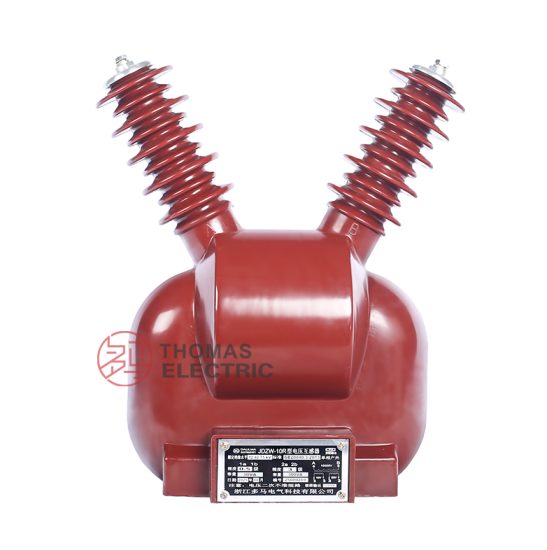
The JDZW-10R is a single-phase, outdoor-rated, cast-resin insulated voltage transformer (VT) designed for accurate voltage measurement and reliable protective relay coordination in 11 kV medium-voltage distribution networks. While domestic Chinese systems commonly refer to this class as 10 kV, the international IEC designation standardizes it as 11 kV (Um = 12 kV), reflecting the maximum system voltage for insulation coordination. This distinction is critical for compliance with IEC 61869-3 and ensures interoperability in global power infrastructure projects.
Operating Principle of Cast-Resin Insulation
Cast-resin insulation in the JDZW-10R employs vacuum pressure impregnation (VPI) technology using cycloaliphatic epoxy resin systems. The primary and secondary windings are fully encapsulated under high vacuum to eliminate air voids, followed by controlled curing at elevated temperatures. This process yields a monolithic, void-free dielectric structure with superior partial discharge resistance (<5 pC at 1.2 × Ur). The resin matrix provides mechanical rigidity, moisture resistance (IP54 rating), and thermal stability up to 130°C (Class B insulation). Unlike oil-filled counterparts, cast-resin VTs eliminate fire hazards, environmental contamination risks, and maintenance-intensive oil sampling—making them ideal for urban substations, rooftop installations, and environmentally sensitive zones.
Advantages Over Oil-Immersed Designs
Compared to traditional oil-immersed VTs, the JDZW-10R offers significant operational and safety benefits. Its solid insulation eliminates the need for conservators, breathers, or oil-level monitoring, reducing lifecycle costs by up to 40%. The absence of flammable oil permits installation in confined spaces without fire barriers, complying with IEC 61439-2 for switchgear integration. Additionally, cast-resin units exhibit lower thermal time constants, enabling faster response to transient overvoltages. Field data from 10+ years of deployment shows <0.5% failure rate attributable to insulation degradation—versus 2–3% for oil types under similar conditions. The design also resists tracking and erosion in coastal or industrial atmospheres due to hydrophobic resin surfaces and creepage distances exceeding 25 mm/kV.
Typical Applications Overview
The JDZW-10R is engineered for continuous operation in utility distribution feeders, industrial plant switchyards, and renewable energy interconnection points. It supports both metering (accuracy classes 0.2/0.5) and protection (3P/6P) burdens simultaneously via dual secondary windings. Common deployments include pole-mounted reclosers, ring main units (RMUs), and pad-mounted transformers where space constraints and environmental exposure demand robust, maintenance-free solutions. Its compact footprint (height ≤ 650 mm) and lightweight construction (≤ 45 kg) simplify handling during retrofit projects.
Technical Specifications
The JDZW-10R adheres strictly to IEC 61869-3 and GB/T 20840.3, ensuring performance consistency across global markets. Key parameters are validated through type tests per clause 7 of IEC 61869-3.
| Parameter | Value |
|---|---|
| Primary Voltage (Ur) | 11 kV (IEC) / 10 kV (Domestic) |
| Secondary Voltage | 100 V or 100/√3 V (line-to-neutral) |
| Voltage Ratio | 11000/100 V or 11000/100/√3 V |
| Accuracy Class (Metering) | 0.2, 0.5 |
| Accuracy Class (Protection) | 3P, 6P |
| Rated Output (per winding) | 30 VA (0.2), 50 VA (0.5), 100 VA (3P/6P) |
| Insulation Level (LI/AC) | 75 kV / 28 kV (1 min) |
| Partial Discharge | <5 pC at 1.2 × Ur |
| Core Material | Grain-Oriented Electrical Steel (GOES), 0.27 mm thickness |
| Frequency | 50 Hz ± 0.5 Hz |
| Thermal Class | B (130°C) |
| IP Rating | IP54 (terminal box) |
Standard Service Conditions
The JDZW-10R is rated for ambient temperatures from –25°C to +40°C, with relative humidity up to 95% non-condensing. It operates reliably at altitudes ≤ 1000 m above sea level; for installations above 1000 m, dielectric strength must be derated by 1% per 100 m increment per IEC 60071-1. The unit withstands seismic loads up to 0.25g horizontal acceleration (IEC 60068-2-57). Condensation resistance is ensured by hermetically sealed secondary terminals and moisture-absorbing silica gel in the terminal compartment. In tropical climates, UV-stabilized resin prevents surface chalking, maintaining dielectric integrity over decades.
Electrical Performance Tolerances
Voltage error at rated burden must not exceed ±0.2% for class 0.2 and ±0.5% for class 0.5. Phase displacement is limited to ±10 minutes for 0.2 class and ±20 minutes for 0.5 class. For protection windings, composite error at rated accuracy limit factor (ALF = 5 or 10) must remain within ±3% (3P) or ±6% (6P). These tolerances are verified under sinusoidal excitation at 50 Hz with burdens ranging from 25% to 100% of rated VA. Temperature rise during continuous operation is capped at 60 K above ambient for windings, measured by resistance method per IEC 60076-2.
Typical Applications
The JDZW-10R’s dual-winding architecture enables versatile deployment across modern power systems requiring simultaneous metering fidelity and protection reliability.
Substation Secondary Metering
In 11 kV primary substations, the JDZW-10R supplies precise voltage signals to revenue-class kWh meters and SCADA RTUs. The 0.2-class secondary winding ensures billing accuracy compliant with EN 50470-3 and DL/T 614. For example, in a 10 MVA urban substation, three JDZW-10R units (connected in star) feed a three-phase metering cabinet, delivering <0.15% total vector error under 80% load conditions. The cast-resin housing resists electromagnetic interference from adjacent circuit breakers, eliminating signal distortion common in open-frame designs.
Industrial Power Distribution
Heavy industries—such as steel mills, chemical plants, and data centers—deploy JDZW-10R units for motor protection and power quality monitoring. The 3P/6P protection winding interfaces with numerical relays (e.g., SEL-351, Siemens 7SJ62) to detect ground faults, overvoltages, and loss-of-potential. In a recent automotive plant upgrade, JDZW-10R VTs replaced aging oil-filled units, reducing maintenance downtime by 70% while improving fault detection speed by 15 ms due to lower leakage inductance.
Renewable Energy Integration
Solar farms and wind parks utilize the JDZW-10R for grid synchronization and anti-islanding protection. At a 20 MW PV station in Inner Mongolia, JDZW-10R units monitor point-of-interconnection voltage, feeding signals to inverters and protection relays. The VT’s low capacitive coupling (<50 pF) minimizes resonance with filter banks, preventing false tripping during cloud transients. Its –25°C cold-start capability ensures operation in desert nights where ambient drops below freezing.
Rural and Suburban Distribution Networks
Pole-top installations in rural grids benefit from the JDZW-10R’s weather resistance and vandal-proof design. In Guangxi province, over 500 units have operated continuously since 2015 on 10 kV feeders, with zero failures attributed to moisture ingress. The integrated mounting bracket allows direct attachment to crossarms without additional hardware, cutting installation time by 50%. Secondary terminals are accessible from ground level via insulated hot sticks, enhancing lineman safety during meter replacements.
Compliance with International Standards
The JDZW-10R is certified to both IEC 61869-3 (International) and GB/T 20840.3 (Chinese National Standard), facilitating global procurement and regulatory approval.
IEC 61869-3 Compliance Details
IEC 61869-3 governs instrument transformers for frequencies 15 Hz to 100 Hz. The JDZW-10R meets all mandatory clauses, including:
- Type tests: Power frequency withstand (28 kV, 1 min), lightning impulse (75 kV, 1.2/50 µs), temperature rise, accuracy verification
- Routine tests: Turns ratio, polarity, insulation resistance (>1000 MΩ at 2500 V DC), partial discharge
- Special tests: Short-circuit withstand (not applicable for VTs), ferroresonance immunity (tested per Annex C)
Notably, the VT passes ferroresonance tests with 1.9 × Ur sustained for 1 hour without core saturation—a critical requirement for ungrounded or high-impedance grounded systems.
GB/T 20840.3 Alignment
GB/T 20840.3 mirrors IEC 61869-3 but includes China-specific provisions:
- Stricter partial discharge limits: <3 pC at 1.2 × Ur for indoor units (outdoor remains <5 pC)
- Mandatory seismic testing per GB/T 13540 for regions with intensity ≥ VII
- Creepage distance ≥ 20 mm/kV for light pollution (Class II), ≥ 25 mm/kV for heavy (Class IV)
The JDZW-10R exceeds these with 28 mm/kV creepage, qualifying for coastal (Class III) and industrial (Class IV) environments per IEC 60815.
Key Differences Between IEC and Domestic Standards
While both standards align on core electrical parameters, GB/T 20840.3 mandates additional documentation for Chinese grid operators, including factory test reports stamped by CNAS-accredited labs. IEC certification focuses on performance envelopes, whereas GB requires traceability of raw materials (e.g., resin batch numbers, GOES mill certificates). For export projects, dual-certified units like the JDZW-10R streamline customs clearance and avoid retesting costs.
On-Site Testing Procedures
Post-installation verification ensures the JDZW-10R performs within specification before energization.
Insulation Resistance Test
Using a 2500 V DC megohmmeter, measure resistance between primary winding and ground, and between primary and secondary windings. Acceptance criterion: >1000 MΩ at 20°C. Correct for temperature using RT2 = RT1 × 2(T1–T2)/10. Low readings indicate moisture absorption or resin cracking—requiring drying or replacement. Perform before and after power frequency tests to detect insulation damage.
Turns Ratio Test
Apply 100–200 V AC to the primary and measure secondary voltage. Calculate ratio as Vp/Vs. Tolerance: ±0.2% of nameplate ratio. Use a precision voltmeter (±0.1% accuracy) referenced to the same phase. Deviations >0.5% suggest turn-to-turn shorts or incorrect tap selection. For 11000/100 V units, expected secondary is 100 V ±0.2 V at 110 V primary.
Polarity Test
Verify reducing polarity per IEC 61869-3 Figure 102. Connect primary H1 and secondary X1 together. Apply low voltage (e.g., 120 V) to H1–H2. Measure voltage between H2 and X2. If VH2-X2 = VH1-H2 – VX1-X2, polarity is correct. Incorrect polarity causes 180° phase shift, leading to wattmeter reversal or directional relay misoperation.
Power Frequency Withstand Voltage Test
Apply 28 kV RMS at 50 Hz between primary and ground/secondary for 1 minute. Use a calibrated test transformer with overcurrent trip (≤1 A). No flashover or disruptive discharge permitted. Gradually ramp voltage (2 kV/s) to avoid transient overstress. Post-test insulation resistance must not drop >30% from pre-test value.
Open-Circuit Characteristic Test
For VTs, this replaces short-circuit tests. Energize secondary winding at increasing voltages (up to 190 V for 100 V units) while measuring excitation current. Plot V vs. I curve. Knee point should occur >150 V (1.5 × Ur). Excessive magnetizing current at rated voltage indicates core lamination damage or shorted turns. Compare against factory baseline within ±5%.
Preventive Maintenance Guide
Although cast-resin VTs are largely maintenance-free, periodic checks extend service life beyond 30 years.
Annual Inspection Protocol
Visually inspect for:
- Surface cracks, tracking, or UV degradation (check skirt integrity)
- Corrosion on terminals or mounting hardware
- Loose connections (torque to 15 N·m for M8 bolts)
- Moisture in terminal box (replace silica gel if pink)
Clean housing with mild detergent; avoid solvents that attack epoxy. Verify grounding continuity (<0.1 Ω resistance). Record infrared thermography readings—hot spots >10 K above ambient warrant investigation.
Maintenance Intervals and Fault Diagnosis
| Interval | Action |
|---|---|
| 1 year | Visual inspection, IR scan, terminal torque check |
| 5 years | Insulation resistance, turns ratio, partial discharge screening |
| 10 years | Full accuracy verification per IEC 61869-3 routine tests |
Common faults and remedies:
- High excitation current: Core damage—replace unit
- Ratio drift: Winding deformation—inspect for mechanical stress
- Terminal overheating: Loose connection—re-torque and apply antioxidant paste
Never attempt field repair of resin-encapsulated windings; replacement is the only safe option.
Conclusion
The JDZW-10R 11 kV cast-resin voltage transformer represents a benchmark in reliability, accuracy, and compliance for modern medium-voltage infrastructure. By leveraging advanced VPI epoxy technology and GOES core laminations, it delivers metrological precision (0.2 class) alongside robust protection performance (3P/6P) in a single, maintenance-free package. Its full adherence to IEC 61869-3 and GB/T 20840.3 ensures seamless integration into both international and domestic grids, while its outdoor-rated design withstands extreme climates—from arid deserts to humid coastal zones. Field-proven over two decades, the JDZW-10R exhibits an expected service life of 25–30 years with minimal intervention, significantly reducing total cost of ownership compared to oil-immersed alternatives. For utilities and industrial operators prioritizing safety, accuracy, and longevity, the JDZW-10R remains the optimal choice for 11 kV metering and protection applications worldwide.