Article Content
Outdoor 21kV Cast-Resin Voltage Transformer JDZW-20 – IEC 61869-3 Compliant
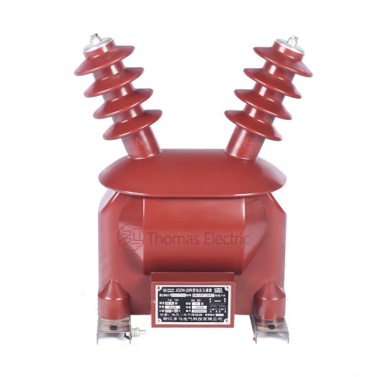
Introduction to the JDZW-20 Voltage Transformer
The JDZW-20 is a single-phase, outdoor-rated cast-resin voltage transformer (VT) designed for accurate voltage measurement and reliable protective relaying in medium-voltage (MV) power systems rated at 21 kV (IEC standard), corresponding to the domestic 20 kV system voltage commonly used in China and other regions adhering to GB standards. This instrument transformer leverages advanced vacuum pressure impregnation (VPI) epoxy resin technology to provide superior dielectric strength, environmental resilience, and long-term operational stability without the fire or leakage hazards associated with traditional oil-immersed designs.
Operating Principle and Cast-Resin Insulation Technology
Voltage transformers operate on the principle of electromagnetic induction, stepping down high primary voltages to standardized secondary levels (typically 100 V or 100/√3 V) suitable for metering instruments, protective relays, and monitoring equipment. In the JDZW-20, the primary and secondary windings are wound concentrically around a high-permeability grain-oriented electrical steel (GOES) core, which minimizes core losses and ensures excellent accuracy under varying load and voltage conditions. The entire magnetic assembly is encapsulated in a solid, void-free epoxy resin matrix using VPI processes. This technique eliminates air pockets that could lead to partial discharges, thereby enhancing dielectric integrity and extending service life. The cast-resin body provides mechanical rigidity, resistance to UV degradation, and immunity to moisture ingress—critical for outdoor installations exposed to rain, dust, and temperature cycling from –40°C to +40°C.
Advantages Over Oil-Immersed Voltage Transformers
Compared to oil-filled VTs, the JDZW-20 offers significant operational and safety benefits. It is maintenance-free, eliminating the need for periodic oil sampling, level checks, or gasket replacements. The absence of flammable oil reduces fire risk, making it suitable for urban substations, indoor switchgear rooms adjacent to public spaces, and environmentally sensitive areas. Additionally, the compact, lightweight design simplifies transportation and installation, while the robust resin housing withstands seismic activity up to 0.3g (per IEC 60068-2-57). Partial discharge levels are consistently below 10 pC at 1.2 × Um/√3 (where Um = 24 kV), ensuring compliance with stringent IEC 61869-3 requirements for accuracy class 0.2S applications.
Typical Application Overview
The JDZW-20 is engineered for deployment in utility distribution networks, industrial plants, renewable energy interconnection points, and rural electrification projects. Its 0.2S accuracy class supports revenue-grade metering, while its thermal and dynamic withstand capabilities ensure reliable performance during system faults. Common configurations include pole-mounted installations on 20 kV feeders, pad-mounted substations, and ring main units (RMUs). Secondary outputs can be tapped for both metering (0.2S) and protection (3P or 6P) burdens simultaneously, enabling dual-function use without compromising accuracy or safety margins.
Technical Specifications
The JDZW-20 voltage transformer is engineered to meet precise electrical and environmental parameters essential for reliable operation in demanding MV networks. All specifications align with IEC 61869-3 and GB/T 20840.3, ensuring global interoperability and performance consistency.
Rated Electrical Parameters
The primary rated voltage is 21 kV (Um = 24 kV), corresponding to the IEC standard system voltage; this equates to the nominal 20 kV used in domestic Chinese grids. Standard voltage ratios include 21,000/100 V and 21,000/√3 : 100/√3 V for grounded systems. Accuracy classes are available as 0.2S for metering and 3P or 6P for protection, with composite error limits of ≤ ±0.2% for 0.2S at 20–120% of rated voltage and burden. Rated outputs range from 30 VA to 100 VA per winding, with thermal limiting output up to 500 VA for short-duration fault conditions. The insulation level is defined by a lightning impulse withstand voltage of 125 kV peak and a power frequency withstand voltage of 50 kV RMS for 1 minute between primary and earth, and 3 kV RMS between secondary terminals and earth.
Environmental and Mechanical Ratings
Designed for outdoor service, the JDZW-20 operates reliably under ambient temperatures from –40°C to +40°C, relative humidity up to 100%, and altitudes not exceeding 1,000 meters above sea level (derating applies above this altitude per IEC 60076-11). The creepage distance exceeds 25 mm/kV (minimum 525 mm) to prevent flashover in polluted environments (Class III pollution per IEC 60815). The housing is made of UV-stabilized cycloaliphatic epoxy resin with hydrophobic surface properties, resisting tracking and erosion. Mounting is via a standard M16 stud base compatible with ANSI C57.12.29 and GB/T 7354 brackets, allowing direct integration into existing 20 kV infrastructure.
Core and Winding Construction Details
The magnetic circuit employs high-grade GOES (M4 or equivalent) laminations with a thickness of 0.27 mm, annealed to reduce hysteresis losses. Core stacking factor exceeds 0.95, minimizing excitation current and improving phase angle accuracy—critical for 0.2S class performance. Secondary windings use enameled copper wire with Class F (155°C) insulation, embedded within the resin matrix to prevent movement-induced fatigue. Terminal blocks are rated for 600 V and feature screw-type connectors compliant with IEC 60947-7-1, supporting conductor sizes from 1.5 mm² to 6 mm². Polarity is marked per IEC 61869-1: reducing polarity with “*” on primary and secondary H1/X1 terminals.
Typical Applications
The JDZW-20 serves as a cornerstone component in modern MV infrastructure, enabling precise voltage monitoring and system protection across diverse grid architectures.
Substation Secondary Metering Systems
In 20/21 kV distribution substations, the JDZW-20 provides the reference voltage for revenue metering panels. Its 0.2S accuracy ensures billing precision even at low loads (as low as 1% of rated voltage), satisfying regulatory requirements in markets like China’s State Grid and European DSOs. When paired with class 0.2S current transformers, the combined metering error remains within ±0.4%, supporting AMI (Advanced Metering Infrastructure) deployments. The VT’s low phase displacement (< ±10 minutes at 0.2S) prevents reactive energy miscalculation, crucial for power factor correction schemes.
Industrial Power Distribution Networks
Large manufacturing facilities often operate internal 20 kV networks fed from utility tie-lines. Here, the JDZW-20 supplies voltage signals to multifunction relays (e.g., SEL-751, Siemens 7SJ62) for overvoltage, undervoltage, and loss-of-potential protection. Its high saturation point (> 2.0 × rated voltage) prevents core distortion during ferroresonance events common in cable-fed systems. The cast-resin design also resists chemical exposure in petrochemical or mining environments where oil-filled units would degrade.
Renewable Energy Integration Points
At solar PV or wind farm interconnection points, the JDZW-20 monitors grid voltage for anti-islanding detection and voltage ride-through compliance (e.g., GB/T 19964, IEC 61400-21). Its fast response time (< 20 ms) and stable ratio under harmonic distortion (THD ≤ 5%) ensure accurate synchronization during grid disturbances. Multiple secondary windings allow simultaneous connection to SCADA RTUs, revenue meters, and protection relays without burden interaction.
Rural and Suburban Distribution Feeders
Pole-mounted JDZW-20 units enable remote voltage monitoring on lightly loaded rural circuits. Their maintenance-free nature reduces OPEX for utilities managing extensive feeder networks. In suburban ring-main systems, they support directional earth-fault protection by providing polarizing voltage to relays such as ABB REF615. The unit’s compact size (height ≈ 650 mm, weight ≈ 45 kg) facilitates installation on standard crossarms without structural reinforcement.
Hybrid Switchgear and RMU Integration
Modern ring main units increasingly incorporate cast-resin VTs directly into SF6 or solid-insulated switchgear. The JDZW-20’s dimensions and terminal layout are compatible with OEM enclosures from companies like Schneider Electric and Siemens, enabling factory-integrated solutions that reduce field commissioning time. Its low partial discharge ensures compatibility with sensitive electronic sensors in digital substations.
Compliance with International Standards
The JDZW-20 is rigorously certified against globally recognized standards, ensuring interoperability, safety, and performance consistency across markets.
IEC 61869-3 Certification Requirements
IEC 61869-3 governs the accuracy, insulation, and testing protocols for inductive voltage transformers. The JDZW-20 meets all clauses for accuracy classes 0.2S, 3P, and 6P, including ratio error (±0.2% max at 0.2S), phase displacement (±10’ max), and composite error under specified burdens. Dielectric tests include 1-minute AC withstand at 50 kV, switching impulse at 125 kV, and partial discharge measurement at 1.2 × Um/√3 (≤10 pC). Thermal stability is verified by continuous operation at 1.2 × rated voltage for 8 hours without exceeding 75 K temperature rise.
Alignment with GB/T 20840.3 and DL/T 726
GB/T 20840.3 mirrors IEC 61869-3 but includes additional requirements for Chinese grid operators, such as stricter pollution performance (creepage ≥ 25 mm/kV) and mandatory type testing per DL/T 726. The JDZW-20 complies with all GB-specific clauses, including short-circuit withstand capability (thermal: 1 s at 16 kA; dynamic: 40 kA peak) and secondary terminal short-circuit proofing. Type test reports are issued by CNAS-accredited labs, ensuring acceptance by State Grid and China Southern Power Grid.
Key Differences Between IEC and Domestic Standards
While IEC 61869-3 focuses on functional performance, GB/T 20840.3 emphasizes environmental robustness and grid-specific fault tolerance. For example, GB requires verification of performance after simulated salt fog exposure (48 hours, 5% NaCl), whereas IEC references general pollution classes. Additionally, GB mandates secondary winding short-circuit tests at 10 × rated current for 1 second—a requirement absent in IEC. The JDZW-20 is engineered to exceed both frameworks, ensuring global deployability without redesign.
On-Site Testing Procedures
Post-installation verification ensures the JDZW-20 performs within specification before energization. All tests follow IEC 61869-3 Annex B and DL/T 726 guidelines.
Insulation Resistance Test
Using a 2,500 V DC megohmmeter, measure insulation resistance between primary winding and earth, and between secondary windings and earth. Acceptance criteria: ≥10,000 MΩ at 20°C. Values below 1,000 MΩ indicate moisture ingress or resin cracking and require investigation. Temperature correction per IEEE 43 should be applied if ambient differs significantly from 20°C.
Turns Ratio and Polarity Verification
Apply a low-voltage AC source (50–100 V) to the primary and measure secondary voltage. Calculate actual ratio and compare to nameplate. Tolerance: ±0.2% for 0.2S class. Simultaneously verify reducing polarity by observing instantaneous voltage direction with an oscilloscope or dedicated polarity tester—H1 and X1 must be in phase.
Power Frequency Withstand Voltage Test
Apply 50 kV RMS at 50 Hz between primary and grounded tank for 1 minute. Secondary terminals must be shorted and grounded. No flashover or disruptive discharge is permitted. This test validates insulation integrity after transport and installation stresses.
Partial Discharge Measurement
At 1.2 × Um/√3 (16.6 kV), measure partial discharge using IEC 60270 methods. Acceptance limit: ≤10 pC. Higher values suggest voids in resin or winding defects. This test is critical for 0.2S class VTs where PD can degrade accuracy over time.
Open-Circuit Characteristic Test
With secondary open, gradually increase primary voltage from 0 to 1.5 × rated (31.5 kV) while recording excitation current. The knee point should exceed 2.0 × rated voltage. Excessive magnetizing current indicates core saturation issues, compromising accuracy during overvoltage events.
Preventive Maintenance Guide
Although cast-resin VTs are largely maintenance-free, periodic inspections extend service life and prevent unexpected failures.
Annual Visual and Functional Inspection
Inspect housing for cracks, UV degradation, or tracking marks. Clean surface with non-abrasive detergent if contamination is visible. Verify terminal tightness (torque: 2.5 N·m for M6 screws). Perform insulation resistance and ratio tests annually in critical applications (e.g., revenue metering). Record trends—declining IR or increasing ratio error may signal internal degradation.
Five-Year Comprehensive Assessment
Every five years, conduct partial discharge measurement and open-circuit characteristic tests. Compare results to baseline commissioning data. If PD increases by >50% or knee point drops below 1.8 × rated voltage, consider replacement. Also inspect mounting hardware for corrosion, especially in coastal areas.
Maintenance Intervals and Fault Diagnosis Table
| Interval | Task | Acceptance Criteria |
|---|---|---|
| Annually | Visual inspection, IR test, ratio check | IR ≥10,000 MΩ; ratio error ≤±0.25% |
| 5 Years | PD test, excitation curve, terminal torque | PD ≤12 pC; knee point ≥1.8× rated |
| As Needed | Fault analysis after system disturbance | No physical damage; post-fault tests within spec |
Common failure modes include terminal corrosion (due to improper sealing), resin cracking from thermal cycling, and secondary winding fatigue from vibration. Most are preventable with proper installation and periodic checks.
Conclusion
The JDZW-20 cast-resin voltage transformer represents a technically mature, standards-compliant solution for 21 kV (20 kV) outdoor applications requiring high metrological accuracy and dependable protection functionality. By leveraging VPI epoxy resin encapsulation and GOES core technology, it delivers exceptional dielectric performance, environmental resilience, and long-term stability—free from the maintenance burdens and safety concerns of oil-filled alternatives. Its certification to both IEC 61869-3 and GB/T 20840.3 ensures seamless integration into global power systems, from urban substations to remote renewable sites. With rigorous on-site testability, a structured preventive maintenance protocol, and a design life exceeding 25–30 years under normal operating conditions, the JDZW-20 provides utilities and industrial operators with a cost-effective, future-proof investment in grid intelligence and reliability. As distribution networks evolve toward digitalization and distributed generation, the JDZW-20’s precision and robustness will remain foundational to accurate energy accounting and system security.
Frequently Asked Questions (FAQ)
Q1: Can the JDZW-20 be used in a 22 kV system?
A: No. The JDZW-20 is rated for Um = 24 kV, corresponding to a maximum system voltage of 21 kV (IEC) or 20 kV (domestic). Operation above 21 kV violates insulation coordination and voids certification.
Q2: Is the JDZW-20 suitable for indoor installations?
A: Yes. While optimized for outdoor use, its cast-resin construction meets indoor fire safety requirements (non-flammable, no toxic fumes). Ensure adequate clearance per IEC 61439-2.
Q3: What is the minimum burden for 0.2S accuracy?
A: Per IEC 61869-3, 0.2S class is guaranteed at burdens from 25% to 100% of rated VA. For a 30 VA unit, maintain load between 7.5 VA and 30 VA.
Q4: How many secondary windings does the JDZW-20 support?
A: Standard models offer one or two independent secondary windings (e.g., 0.2S/3P), each with separate terminals and isolation. Custom configurations are available.
Q5: Does the JDZW-20 require grounding of the secondary neutral?
A: Yes. In wye-connected systems, the secondary neutral (X2) must be grounded at a single point per IEC 61869-1 to prevent capacitive coupling and ensure safety.