Article Content
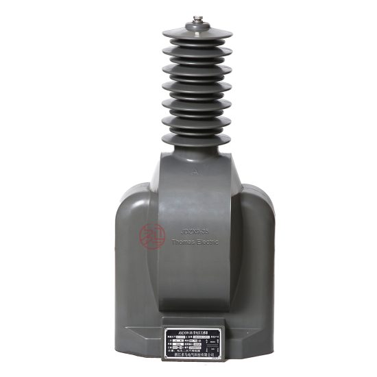
JDZW-35 33kV Cast-Resin Voltage Transformer for Substation Metering and Protection – IEC 61869-3 Certified
Introduction to the JDZW-35 Voltage Transformer
The JDZW-35 is a single-phase, outdoor-type cast-resin voltage transformer (VT) engineered for reliable operation in 33 kV power systems—commonly designated as 35 kV in legacy Chinese grid nomenclature. This instrument transformer leverages advanced vacuum pressure impregnation (VPI) epoxy resin technology to encapsulate its primary and secondary windings, ensuring superior dielectric strength, environmental resilience, and long-term operational stability without the fire or leakage hazards associated with oil-immersed alternatives.
Operating Principle of Cast-Resin Insulation
Cast-resin insulation in the JDZW-35 employs a thermosetting epoxy compound that fully encapsulates the high-voltage winding, low-voltage winding, and magnetic core assembly under vacuum and pressure. This process eliminates air voids and moisture ingress pathways, resulting in a homogeneous dielectric barrier with a relative permittivity of approximately 4.5 and volume resistivity exceeding 1×10¹⁴ Ω·cm at 20°C. The resin matrix provides mechanical rigidity, thermal conductivity (~0.8 W/m·K), and resistance to tracking and erosion under polluted or humid conditions. Unlike oil-filled VTs, which rely on liquid dielectric and require periodic oil testing, the solid insulation system of the JDZW-35 is maintenance-free over its service life, making it ideal for remote or unmanned substations.
Advantages Over Oil-Immersed Designs
Compared to traditional oil-immersed voltage transformers, the JDZW-35 offers significant operational and safety benefits. Its non-flammable epoxy resin construction eliminates fire risk, satisfying stringent safety codes in urban or indoor substations. The absence of oil also removes concerns about leaks, environmental contamination, and the need for oil sampling or gas chromatography analysis. Furthermore, the compact physical footprint—typically 30–40% smaller than equivalent oil units—reduces space requirements and simplifies transportation and handling. Thermal performance is enhanced through uniform heat dissipation across the resin body, with a maximum hotspot temperature rise limited to 60 K above ambient under rated load, per IEC 61869-3. These attributes collectively reduce lifecycle costs while improving reliability in harsh climates.
Typical Applications Overview
The JDZW-35 is primarily deployed in outdoor 33 kV (35 kV nominal) distribution and transmission substations where accurate voltage measurement and protective relay coordination are critical. It supports both metering circuits (Class 0.2 or 0.5 accuracy) and protection relays (Class 3P or 6P), enabling dual functionality from a single unit. Common installations include ring-main units, switchgear bays, and pole-mounted configurations in industrial parks, utility feeders, and renewable energy interconnection points. Its robust design withstands seismic activity up to 0.3g and pollution severity levels up to IV (IEC 60815), making it suitable for coastal, desert, and high-altitude environments.
Technical Specifications
The JDZW-35 adheres to precise electrical and mechanical parameters defined by international and national standards. Below is a comprehensive specification table followed by detailed environmental and operational constraints.
| Parameter | Value |
|---|---|
| System Voltage (Um) | 36 kV (IEC), 35 kV (GB) |
| Rated Primary Voltage | 33,000 / √3 V (phase-to-ground) |
| Rated Secondary Voltage | 100 / √3 V or 110 / √3 V (configurable) |
| Voltage Ratio | 33,000 / √3 : 100 / √3 V (standard) |
| Accuracy Classes | Metering: 0.2, 0.5; Protection: 3P, 6P |
| Rated Output (per burden) | 30 VA (0.2), 50 VA (0.5), 100 VA (3P/6P) |
| Insulation Level (LI/AC) | 170 kV / 70 kV (per IEC 60071-1) |
| Power Frequency Withstand Voltage | 70 kV rms for 1 min (primary to ground) |
| Impulse Withstand Voltage (1.2/50 μs) | 170 kV peak |
| Core Material | Grain-Oriented Electrical Steel (GOES), M4 grade |
| Insulation System | VPI Epoxy Resin, Class F (155°C) |
| Ambient Temperature Range | –40°C to +40°C |
| Maximum Altitude | 1,000 m (derating required above) |
| Relative Humidity | Up to 95% non-condensing |
Standard Service Conditions
The JDZW-35 is rated for continuous operation under standard service conditions as defined in IEC 61869-3 Clause 5. Ambient temperature must remain between –40°C and +40°C, with a 24-hour average not exceeding +35°C. Relative humidity may reach 95% provided condensation does not occur on the housing surface. Installation altitude is limited to 1,000 meters above sea level; for sites between 1,000–3,000 m, the power frequency withstand voltage must be reduced by 1% per 100 m increment above 1,000 m. The transformer is designed for vertical mounting with the primary terminal facing upward, and requires a minimum creepage distance of 25 mm/kV (phase-to-ground) to meet pollution degree IV requirements.
Electrical Performance Tolerances
Voltage ratio error must remain within ±0.2% for Class 0.2 and ±0.5% for Class 0.5 under 25–100% of rated burden. Phase displacement is limited to ±10 minutes for Class 0.2 and ±20 minutes for Class 0.5. For protection classes (3P/6P), composite error must not exceed 3% or 6%, respectively, at rated voltage and specified burden under fault conditions. Burden tolerance is ±10% of declared VA rating. These tolerances are verified during factory type tests and must be reconfirmed during commissioning.
Typical Applications
The JDZW-35 serves diverse roles across modern power infrastructure, combining metrological precision with ruggedness for outdoor deployment.
Substation Secondary Metering
In 33 kV primary substations, the JDZW-35 supplies scaled-down voltage signals to revenue-grade kWh meters, demand recorders, and SCADA RTUs. Its Class 0.2 accuracy ensures compliance with regulatory billing requirements (e.g., China’s DL/T 448). The transformer’s low phase displacement minimizes reactive power measurement errors, critical for power factor correction schemes. A typical configuration includes dual secondary windings—one dedicated to metering (0.2/30 VA) and another to protection (3P/100 VA)—isolated via separate terminals to prevent burden interaction.
Industrial Power Distribution
Large manufacturing facilities often operate internal 35 kV networks fed from utility tie-lines. Here, the JDZW-35 enables precise monitoring of incoming voltage quality, harmonic distortion, and unbalance. Its cast-resin construction resists chemical fumes and particulate contamination common in steel mills or chemical plants. Integration with digital relays (e.g., SEL-351) allows for undervoltage, overvoltage, and loss-of-potential protection, enhancing process continuity and equipment safety.
Renewable Energy Integration
Solar farms and wind parks frequently connect to the grid via 35 kV collector systems. The JDZW-35 provides voltage feedback for anti-islanding protection, synchronization checks, and power quality compliance (e.g., GB/T 19964). Its fast transient response (<5 ms rise time) captures voltage sags during cloud transients or turbine trips. The transformer’s immunity to DC offset—critical in inverter-based resources—ensures stable operation during asymmetrical faults.
Rural and Suburban Distribution Networks
In remote areas with limited maintenance access, the JDZW-35’s maintenance-free design reduces operational overhead. Mounted on poles or pad-mounted switchgear, it supports automated feeder reclosers and sectionalizers. Its wide temperature tolerance accommodates extreme diurnal swings in desert or alpine regions. Utilities leverage its long service life (25+ years) to defer capital expenditures while maintaining ANSI C57.13-comparable performance.
Hybrid Substation Retrofits
Legacy substations upgrading from oil-filled VTs often select the JDZW-35 due to dimensional compatibility and identical terminal spacing. This facilitates drop-in replacement without structural modifications. The absence of oil containment basins simplifies site remediation and reduces environmental liability, accelerating decommissioning timelines.
Compliance with International Standards
The JDZW-35 is engineered to satisfy both global and domestic regulatory frameworks, ensuring interoperability and safety.
IEC 61869-3 Compliance Details
Per IEC 61869-3:2011 (Instrument transformers – Part 3: Additional requirements for inductive voltage transformers), the JDZW-35 undergoes rigorous type, routine, and special tests. Key requirements include: temperature rise ≤60 K (resistance method), partial discharge <10 pC at 1.2 Um/√3, and short-circuit withstand capability for 1 second at 25× rated current. Accuracy verification follows Annex B procedures using calibrated reference standards traceable to national labs. The standard mandates clear marking of rated insulation level (e.g., “LI 170 AC 70”) and terminal polarity (“•” symbol).
Alignment with GB/T 20840.3
China’s GB/T 20840.3-2013 mirrors IEC 61869-3 but includes localized provisions. Notably, GB permits 35 kV as the nominal system voltage (vs. IEC’s 33 kV), though insulation levels remain identical. GB also specifies additional seismic test protocols (horizontal acceleration 0.2g–0.3g) and requires flame retardancy certification (UL 94 V-0 equivalent). Factory test reports must be issued by CNAS-accredited labs, and nameplates must display CCC marking if sold domestically.
Key Differences Between IEC and Domestic Standards
While technical performance aligns closely, procedural differences exist. IEC emphasizes functional safety and lifecycle documentation, whereas GB focuses on local environmental resilience (e.g., salt fog resistance per GB/T 2423.17). Accuracy class notation is identical, but GB allows 110/√3 V secondary outputs more commonly than IEC markets. Crucially, both standards prohibit ferroresonance in VTs; the JDZW-35 mitigates this via core saturation control and optional damping resistors.
On-Site Testing Procedures
Commissioning and periodic verification require standardized field tests to validate integrity and performance.
Insulation Resistance Test
Using a 2,500 V DC megohmmeter, measure insulation resistance between primary winding and ground, and between secondary windings and ground. Acceptance criteria: ≥1,000 MΩ at 20°C. Correct for temperature using RT2 = RT1 × 2(T1–T2)/10. Values below 500 MΩ indicate moisture ingress or resin degradation and warrant further investigation via tan delta or PD testing.
Turns Ratio Test
Apply 100–200 V AC to the primary and measure secondary voltage with a calibrated voltmeter (±0.1% accuracy). Calculate ratio error: [(Vp/Vs)measured – (Vp/Vs)nominal] / (Vp/Vs)nominal × 100%. Tolerance: ±0.2% for Class 0.2, ±0.5% for Class 0.5. Use a ratio bridge (e.g., Omicron CT Analyzer) for highest precision.
Polarity Test
Verify reducing polarity using the DC kick method: briefly apply 6–12 V DC to the primary and observe secondary voltage deflection on an analog meter. A momentary positive kick confirms correct polarity (dot-to-dot connection). Incorrect polarity causes 180° phase reversal, leading to metering errors or relay misoperation. Digital multimeters with min/max capture can substitute if analog meters are unavailable.
Power Frequency Withstand Voltage Test
Apply 70 kV rms at 50 Hz between primary and grounded tank/secondary for 1 minute. Leakage current must remain <3 mA. This test validates insulation integrity post-transportation. If breakdown occurs, inspect for surface tracking or internal voids. Never perform this test if insulation resistance is <1,000 MΩ.
Open-Circuit Characteristic Test
With secondary open, gradually increase primary voltage from 0 to 190% of rated (62.7 kV phase-to-ground). Record excitation current. A sharp current rise above 120% indicates core saturation or turn-to-turn faults. Compare with factory curves; deviation >10% warrants core inspection. This test is critical for detecting winding deformation after seismic events.
Preventive Maintenance Guide
Although cast-resin VTs require minimal maintenance, scheduled inspections extend service life and prevent failures.
Periodic Inspection Protocol
Conduct annual visual and electrical checks: inspect housing for cracks, UV degradation, or tracking marks; verify terminal tightness (torque: 15 N·m for M10 bolts); clean porcelain or silicone sheds with deionized water if pollution layer exceeds 0.1 mg/cm² ESDD. Perform insulation resistance and ratio tests biennially. Document all readings in asset management systems for trend analysis.
Maintenance Intervals and Fault Diagnosis
Follow this schedule:
| Interval | Action |
|---|---|
| Annual | Visual inspection, IR scan (hotspots >10 K above ambient indicate issues) |
| Biennial | Insulation resistance, turns ratio, polarity verification |
| 5-Year | Full IEC 61869-3 routine test suite (including tan delta if accessible) |
| Post-Fault | Open-circuit test, PD measurement if equipment available |
Common faults include secondary winding open-circuit (causing ferroresonance), resin cracking (from thermal cycling), and terminal corrosion. Diagnose via abnormal noise (humming indicates core issues) or erratic meter readings.
Conclusion
The JDZW-35 33 kV cast-resin voltage transformer represents a mature, standards-compliant solution for outdoor substation applications demanding high reliability and minimal lifecycle costs. By leveraging VPI epoxy resin insulation and GOES magnetic cores, it achieves exceptional dielectric strength, thermal stability, and environmental resistance—outperforming oil-immersed alternatives in safety and maintenance requirements. Its dual accuracy classes (0.2/3P) enable seamless integration into both revenue metering and protection schemes, while strict adherence to IEC 61869-3 and GB/T 20840.3 ensures global acceptance and interoperability. Field-proven across diverse climates—from arid deserts to humid coastal zones—the JDZW-35 delivers consistent performance with negligible drift over decades. With a design life of 25–30 years and no requirement for fluid monitoring or replenishment, it significantly reduces operational expenditure for utilities and industrial operators. When installed and maintained per manufacturer guidelines, the JDZW-35 provides a robust foundation for accurate voltage measurement, system protection, and grid modernization initiatives well into the future.
Frequently Asked Questions (FAQ)
Q1: Can the JDZW-35 be used in 35 kV systems even though it’s rated 33 kV?
Yes. The 33 kV rating aligns with IEC’s highest system voltage (Um = 36 kV), while 35 kV is the nominal operating voltage in Chinese grids. The insulation level (LI 170/AC 70) covers both, making it fully compatible.
Q2: What is the acceptable insulation resistance value during maintenance?
Minimum 1,000 MΩ at 20°C using a 2,500 V DC megger. Values below 500 MΩ indicate potential moisture ingress and require investigation.
Q3: How often should turns ratio testing be performed?
Biennially during preventive maintenance, or immediately after any fault event, transportation, or physical impact.
Q4: Is ferroresonance a concern with the JDZW-35?
The design minimizes risk via controlled core saturation, but installing a 100–500 Ω damping resistor across one secondary winding is recommended in isolated-neutral systems.
Q5: Can the secondary output be changed from 100/√3 V to 110/√3 V?
Only if specified at order; the winding is fixed during manufacturing. Verify nameplate before installation.
Q6: What torque should be used on terminal bolts?
15 N·m for M10 stainless steel bolts. Over-torquing can crack the resin flange; under-torquing increases contact resistance and heating.