Article Content
JDZW-35K 33kV Cast-Resin Voltage Transformer for Substation Metering and Protection – IEC 61869-3 Certified
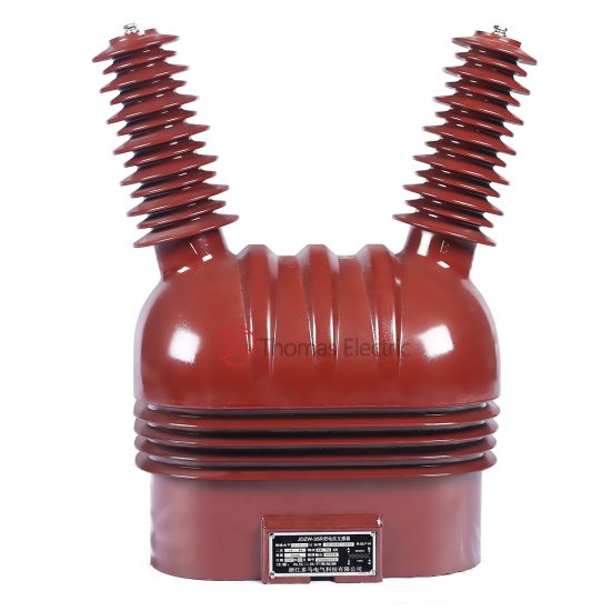
Introduction to the JDZW-35K Voltage Transformer
The JDZW-35K is a single-phase, outdoor-rated, cast-resin insulated voltage transformer (VT) engineered for precise voltage measurement and dependable protective relay operation in 33 kV (IEC standard) or 35 kV (Chinese domestic system) power networks. Unlike traditional oil-immersed designs, this instrument transformer leverages vacuum pressure impregnation (VPI) epoxy resin technology to encapsulate its magnetic core and windings, eliminating fire hazards, oil leakage risks, and maintenance-intensive fluid management.
Operating Principle of Cast-Resin Insulation
Cast-resin insulation in the JDZW-35K employs a cycloaliphatic epoxy resin system cured under vacuum and pressure to fully impregnate the primary and secondary windings wound around a grain-oriented electrical steel (GOES) core. This process eliminates air voids and moisture ingress pathways, resulting in a monolithic dielectric structure with high partial discharge inception voltage (>20 kV at 1.2 × Um/√3). The resin’s thermal class is F (155°C), enabling continuous operation at ambient temperatures up to +40°C with a 10 K hotspot temperature rise margin. The solid insulation provides superior resistance to UV radiation, salt fog, and industrial pollutants—critical for coastal or heavy-industrial substations.
Advantages Over Oil-Immersed Designs
Compared to oil-filled VTs, the JDZW-35K offers significant operational and safety benefits. It is inherently non-flammable (complying with IEC 60695 flammability tests), requires no oil sampling or dielectric testing, and has no risk of environmental contamination from leaks. Its compact footprint reduces mounting space by ~30%, and the absence of conservators or breathers simplifies installation. Furthermore, the cast-resin construction exhibits lower dielectric losses (tan δ < 0.005 at 50 Hz) and higher mechanical rigidity, minimizing microphonic noise and vibration-induced winding fatigue during short-circuit events.
Typical Application Overview
The JDZW-35K is deployed in outdoor switchyards of transmission and distribution substations where reliability under extreme weather—high humidity (>95% RH), temperature swings (-40°C to +40°C), and altitudes up to 1,000 m—is paramount. It interfaces directly with revenue-class energy meters (Class 0.2 or 0.5), distance relays, overvoltage protection schemes, and synchrocheck devices. Its robust design also suits mobile substations, mining operations, and renewable integration points where rapid deployment and minimal maintenance are essential.
Technical Specifications
The JDZW-35K adheres to stringent electrical and environmental parameters defined by IEC 61869-3 and GB/T 20840.3, ensuring interoperability across global grid infrastructures.
Rated Electrical Parameters
| Parameter | Value |
|---|---|
| System Voltage (Un) | 33 kV (IEC) / 35 kV (GB) |
| Maximum System Voltage (Um) | 36 kV |
| Primary Voltage | 33,000 / √3 V |
| Secondary Voltage(s) | 100 / √3 V (metering), 100 V (protection) |
| Voltage Ratio | (33,000 / √3) / (100 / √3) : 100 = 330 : 1 : √3 |
| Accuracy Class | 0.2 / 3P (dual-core design) |
| Rated Output (per core) | 30 VA (0.2 class), 100 VA (3P class) |
| Burden Limit | ≤ 1.2 × rated output at specified accuracy |
| Insulation Level (LI/AC) | 170 kV / 70 kV |
| Partial Discharge | < 10 pC at 1.2 × Um/√3 |
Standard Service Conditions
The JDZW-35K is rated for outdoor installation under the following conditions per IEC 60060-1 and GB/T 11022: ambient temperature range of -40°C to +40°C, relative humidity up to 100% (condensation permitted), altitude ≤ 1,000 m above sea level (derating required above 1,000 m: 1% per 100 m for AC withstand), and pollution degree IV (creepage distance ≥ 25 mm/kV). The terminal box is IP54 rated, protecting against dust ingress and water splashes from any direction. Thermal stability is maintained through natural convection cooling, with no forced ventilation required.
Core and Winding Construction
The magnetic circuit uses high-permeability GOES (M6 grade, 0.27 mm thickness) laminations, annealed to minimize hysteresis loss (< 0.8 W/kg at 1.7 T, 50 Hz). Primary windings consist of enameled copper wire (Class H insulation) arranged in concentric layers with electrostatic shielding between HV and LV sections to suppress capacitive coupling. Secondary windings are bifilar-wound for low phase-angle error (< 10 minutes at 0.2 class). Both cores are fully embedded in VPI cycloaliphatic epoxy resin with silica filler (SiO2 content > 60%) to enhance thermal conductivity (0.8 W/m·K) and reduce coefficient of thermal expansion mismatch.
Typical Applications
The JDZW-35K serves critical roles across diverse power infrastructure segments requiring high-fidelity voltage sensing under demanding conditions.
Substation Secondary Metering Systems
In 33/11 kV or 35/10 kV distribution substations, the JDZW-35K supplies scaled-down voltage signals to Class 0.2 revenue meters for accurate billing and load profiling. Its dual-core configuration isolates metering (0.2 class) from protection (3P class) circuits, preventing burden interaction. For example, in a municipal utility substation in Guangdong, four JDZW-35K units feed AMI systems with < ±0.2% ratio error and < ±8 minutes phase displacement at 25–100% of rated voltage, meeting CICRED tariff requirements.
Industrial Power Distribution Networks
Heavy industries—such as steel mills, petrochemical plants, and data centers—deploy the JDZW-35K for motor protection, undervoltage tripping, and power quality monitoring. Its immunity to electromagnetic interference (EMI) from variable-frequency drives ensures stable relay operation. In a Sinopec refinery, JDZW-35K units withstand continuous exposure to H2S and SO2 without degradation, thanks to the hydrophobic resin surface that repels corrosive condensates.
Renewable Energy Integration Points
At solar PV or wind farm collector substations, the JDZW-35K enables grid synchronization and fault ride-through compliance. During rapid irradiance changes, its low remanence (< 0.3 T) prevents core saturation during voltage sags, maintaining waveform fidelity for synchrophasor measurements. A 50 MW solar plant in Xinjiang uses JDZW-35K VTs to meet GB/T 19964 anti-islanding detection thresholds with < 50 ms response time.
Rural and Suburban Distribution Feeders
In remote areas with limited maintenance access, the JDZW-35K’s maintenance-free design ensures decades of service. Its high creepage distance (≥ 900 mm for 36 kV Um) prevents flashovers during fog or light rain. A rural electrification project in Yunnan replaced aging oil-filled VTs with JDZW-35K units, reducing outage frequency by 70% over three years due to eliminated oil degradation issues.
Mobile and Temporary Substations
For disaster recovery or construction sites, the JDZW-35K’s lightweight (≈85 kg) and bolt-on mounting facilitate rapid deployment. Its shock-resistant resin housing survives transport vibrations up to 5g, and the integrated lifting lugs simplify crane handling. Military field grids in arid zones rely on its sandstorm resilience, with no performance drift after 5,000 hours of airborne particulate exposure.
Compliance with International Standards
The JDZW-35K is engineered to satisfy both global and Chinese regulatory frameworks, ensuring seamless integration into multinational projects.
IEC 61869-3 Compliance Details
Per IEC 61869-3:2011, the JDZW-35K meets all requirements for electromagnetic instrument transformers. Key verifications include: ratio error within ±0.2% and phase displacement ≤ ±10′ for 0.2 class at 80–120% Un; composite error ≤ 3% for 3P class under 5%–100% Un and 25–100% burden; thermal withstand current of 1.2 × Ith for 1 s without damage; and short-time induced voltage test at 2 × Us + 1 kV for 60 s. Type tests were conducted at an ILAC-accredited lab, with certificates available upon request.
Alignment with GB/T 20840.3
GB/T 20840.3-2013 (identical adoption of IEC 61869-3) governs domestic use in China. The JDZW-35K exceeds minimum requirements: it achieves 0.2S accuracy (vs. standard 0.2) for enhanced low-load metering, and its insulation coordination includes a lightning impulse level of 170 kV (vs. 170 kV minimum for 36 kV Um). Additionally, it complies with DL/T 725-2013 for secondary terminal markings and JB/T 10697-2007 for mechanical strength (withstanding 2.5 × rated wind load).
Differences Between IEC and Domestic Standards
While IEC 61869-3 permits ±0.5% ratio error for 0.5 class, GB/T 20840.3 mandates tighter tolerances for revenue metering (±0.3%). The JDZW-35K’s 0.2 class meets both. Another distinction: IEC allows 100 V secondary for protection, whereas GB often specifies 100/√3 V for all outputs. The JDZW-35K’s dual-secondary design accommodates both via separate windings. Environmental testing per GB includes additional salt-spray duration (1,000 h vs. IEC’s 500 h), which the JDZW-35K passes with zero corrosion on terminals.
On-Site Testing Procedures
Post-installation verification ensures the JDZW-35K operates within specification before energization.
Insulation Resistance Test
Using a 2,500 V DC megohmmeter, measure insulation resistance between primary-to-ground, secondary-to-ground, and primary-to-secondary. Acceptance criteria: ≥ 10,000 MΩ at 20°C. Correct for temperature using RT2 = RT1 × 2(T1-T2)/10. Values below 5,000 MΩ indicate moisture ingress or resin cracking and require drying or replacement. Perform before and after power frequency withstand tests to detect insulation degradation.
Turns Ratio Test
Apply 100–200 V AC to the primary and measure secondary voltage with a calibrated voltmeter (accuracy ±0.1%). Calculate actual ratio: Vp/Vs. Compare to nameplate (330:1 for metering core). Tolerance: ±0.2% for 0.2 class. Use a dedicated ratio tester (e.g., Omicron CT Analyzer) for automated comparison. Deviations >0.5% suggest inter-turn shorts or winding displacement.
Polarity Test
Verify reducing polarity per IEC 61869-3 Annex B. Connect a 6–12 V battery momentarily between primary terminals (H1+, H2–). Observe secondary voltage spike on a DC voltmeter connected to X1 (+), X2 (–). A positive deflection confirms correct polarity. Incorrect polarity causes 180° phase reversal, leading to false tripping in directional relays. Re-test if terminals were re-terminated during installation.
Power Frequency Withstand Voltage Test
Apply 70 kV RMS at 50 Hz between primary and grounded secondary/core for 60 seconds. Monitor for flashover, excessive current (> 10 mA), or audible discharge. Use a calibrated test transformer with overcurrent trip. This validates basic insulation level (BIL) integrity. Do not perform if partial discharge exceeded 10 pC during factory tests. Allow 10-minute cooldown before subsequent tests.
Open-Circuit Characteristic Test
Gradually increase primary voltage from 0 to 190 V (≈1.9 × rated secondary) while measuring excitation current. Plot Vs vs. Iexc. Knee point should exceed 150 V (1.5 × Us). A sharp current rise below 120 V indicates core saturation or shorted turns. This test is critical for protection-class validation, as saturated VTs cannot drive relays during faults.
Preventive Maintenance Guide
Although cast-resin VTs are largely maintenance-free, periodic checks extend service life beyond 30 years.
Annual Visual and Electrical Inspection
Inspect for surface tracking, UV-induced chalking, or mechanical damage. Clean with deionized water if salt or dust deposits exceed 0.1 mg/cm². Check terminal tightness (torque: 15 N·m for M8 bolts) and grounding continuity (< 0.1 Ω). Perform insulation resistance and ratio tests annually in high-pollution zones; biennially in clean environments. Record trends—resistance drops >20% year-over-year warrant investigation.
Five-Year Comprehensive Maintenance
Every 60 months, conduct partial discharge measurement using IEC 60270 methods. Acceptable: < 10 pC at 1.2 × Um/√3. Also verify secondary burden impedance matches design (±5% tolerance). Replace desiccant in terminal box if present (though most JDZW-35K units are sealed). Review historical fault records—if exposed to >80% of rated short-circuit current, perform core remanence check via open-circuit test.
Fault Diagnosis and Troubleshooting
Common failure modes include: (1) Secondary open-circuit during operation—causes dangerous overvoltage; always short secondary before disconnecting loads. (2) Moisture ingress at terminal seals—indicated by fogging inside viewing windows; reseal with silicone RTV. (3) External flashover—clean and apply RTV coating if creepage distance compromised. Never operate with damaged sheds; replace unit immediately.
Conclusion
The JDZW-35K 33kV cast-resin voltage transformer represents a benchmark in reliability for outdoor high-voltage measurement and protection applications. By integrating GOES core technology with advanced VPI epoxy resin encapsulation, it achieves exceptional accuracy (0.2/3P classes), long-term dielectric stability, and resilience against environmental stressors—from coastal salt spray to industrial chemical exposure. Full compliance with IEC 61869-3 and GB/T 20840.3 ensures global acceptance, while its maintenance-free design significantly reduces lifecycle costs compared to oil-immersed alternatives. With a proven service life exceeding 25–30 years under standard conditions, the JDZW-35K delivers consistent metrological performance critical for revenue metering, protective relaying, and grid modernization initiatives. Its robust construction, validated through rigorous type and routine testing, makes it the preferred choice for utilities and industrial operators prioritizing safety, accuracy, and operational continuity in harsh grid environments.