Article Content
Outdoor 33kV Cast-Resin Voltage Transformer JLS-35K – IEC 61869-3 Compliant
Introduction to the JLS-35K Voltage Transformer
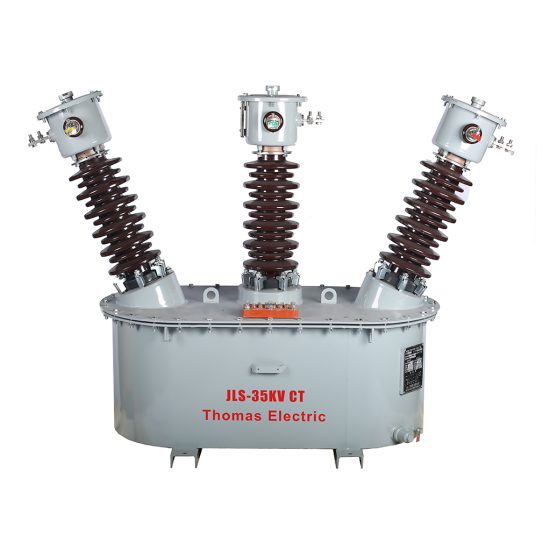
The JLS-35K is a single-phase, outdoor-rated cast-resin insulated Voltage Transformer (VT) engineered for precise voltage measurement and dependable protective relaying in 33 kV (IEC-standard) or 35 kV (domestic nominal) medium-voltage power systems. Designed for deployment in utility substations, industrial facilities, and renewable energy interconnection points, this instrument transformer leverages advanced vacuum pressure impregnation (VPI) epoxy resin technology to deliver superior dielectric performance, environmental resilience, and long-term operational stability without the fire hazards or maintenance demands associated with oil-filled alternatives.
Operating Principle of Cast-Resin Insulation
Cast-resin insulation in the JLS-35K employs a high-purity cycloaliphatic epoxy resin system cured under vacuum and pressure to fully encapsulate the primary and secondary windings along with the GOES (grain-oriented electrical steel) magnetic core. This monolithic structure eliminates air voids and moisture ingress pathways, providing uniform electric field distribution and exceptional partial discharge resistance—typically below 5 pC at 1.2 × Um/√3. The resin’s high thermal conductivity (≈0.2 W/m·K) facilitates efficient heat dissipation during continuous operation, while its mechanical rigidity protects internal components from vibration and seismic stress. Unlike oil-immersed VTs, the solid dielectric requires no periodic oil sampling, degassing, or tank integrity checks, significantly reducing lifecycle costs.
Advantages Over Oil-Immersed Designs
The JLS-35K’s cast-resin construction offers distinct technical advantages in outdoor environments. First, it is inherently non-flammable (compliant with IEC 60695 flammability tests), eliminating fire risks near combustible materials—a critical consideration in urban substations or indoor switchgear rooms. Second, the absence of liquid insulation removes concerns about leakage, freezing at low ambient temperatures (down to –40°C), or expansion/contraction cycles that compromise gasket seals. Third, the compact physical footprint—enabled by higher dielectric strength of epoxy versus oil—allows for easier integration into space-constrained installations. Finally, the sealed design ensures stable accuracy over decades, as moisture absorption or cellulose degradation (common in oil-paper systems) cannot occur.
Typical Application Overview
This VT is primarily deployed in 33 kV transmission and distribution networks where accurate voltage transformation is required for revenue metering (Class 0.2 or 0.5), protective relaying (Class 3P or 6P), and synchro-check functions. Common configurations include single-pole mounting on overhead line structures, bus support insulators in outdoor switchyards, or within metal-enclosed ring main units (RMUs). Its robust design withstands pollution severity up to IV (per IEC 60815), making it suitable for coastal, industrial, and desert environments.
Technical Specifications
The JLS-35K adheres to stringent electrical and mechanical parameters defined by international and domestic standards. Below is a comprehensive specification table followed by detailed service condition requirements.
| Parameter | Value |
|---|---|
| Model | JLS-35K |
| System Voltage (Un) | 33 kV (IEC) / 35 kV (Domestic) |
| Highest System Voltage (Um) | 36 kV |
| Primary Voltage | 33,000 / √3 V (phase-to-ground) |
| Secondary Voltage(s) | 100 / √3 V (metering), 100 V (protection) |
| Voltage Ratio | 33,000 / √3 : 100 / √3 : 100 V |
| Accuracy Class | 0.2 / 3P or 0.5 / 6P (dual burden) |
| Rated Output (per class) | 30 VA (0.2), 50 VA (3P) |
| Insulation Level (LI/AC) | 170 kV / 70 kV |
| Short-Time Thermal Current | 1 s @ 100 A (secondary short-circuit) |
| Frequency | 50 Hz ± 0.5 Hz |
| Core Material | GOES CRGO silicon steel, 0.27 mm thickness |
| Insulation System | VPI cycloaliphatic epoxy resin, UL 94 V-0 rated |
| Ambient Temperature Range | –40°C to +40°C |
| Altitude Limit | ≤ 1,000 m (derating above 1,000 m per IEC 60071-2) |
Standard Service Conditions
The JLS-35K is rated for continuous operation under standard atmospheric conditions as defined in IEC 61869-3 Clause 4. Ambient temperature must remain between –40°C and +40°C, with daily mean not exceeding +35°C. Relative humidity may reach 100% provided condensation does not form on external surfaces—achieved via hydrophobic shed geometry and creepage distance ≥ 25 mm/kV (phase-to-ground). Installation altitude must not exceed 1,000 meters; for sites between 1,000–2,000 m, the power frequency withstand voltage must be reduced by 1% per 100 m above 1,000 m. The transformer assumes symmetrical three-phase system operation with total harmonic distortion (THD) ≤ 5%.
Electrical Performance Tolerances
Voltage error and phase displacement are tightly controlled per accuracy class. For Class 0.2 at 25–100% of rated voltage and 25–100% of rated burden, voltage error must not exceed ±0.2%, and phase error must be within ±10 minutes. For Class 3P under fault conditions (up to 190% of rated voltage), voltage error tolerance widens to ±3%, with phase error ≤ ±120 minutes. These tolerances ensure reliable operation of digital relays and revenue-class meters even during transient overvoltages. The magnetizing current at rated voltage is typically < 0.5 mA, minimizing loading effects on the primary circuit.
Typical Applications
The JLS-35K serves diverse roles across modern power infrastructure, leveraging its dual-accuracy output and outdoor durability.
Substation Secondary Metering
In 33 kV transmission substations, the JLS-35K provides isolated, scaled-down voltage signals to revenue metering systems compliant with IEC 62053-22. Its Class 0.2 secondary winding drives kWh meters with guaranteed accuracy over a 10:1 load range (e.g., 3–30 VA). The transformer’s low phase error (< 5 minutes at 100% load) ensures precise power factor calculation, critical for tariff billing. Mounted directly on bus supports, it eliminates the need for separate potential dividers, reducing installation complexity and failure points.
Industrial Power Distribution
Large manufacturing plants often operate 35 kV internal distribution networks fed from utility tie-lines. Here, the JLS-35K supplies voltage inputs to multifunction protection relays (e.g., overvoltage, undervoltage, directional earth fault) using its Class 3P winding. The 50 VA output capacity supports multiple relay coils simultaneously without accuracy degradation. Its cast-resin body resists chemical fumes and particulate contamination common in steel mills or chemical processing facilities, maintaining dielectric integrity where oil-filled units would degrade.
Renewable Energy Integration
Solar farms and wind parks frequently connect to the grid via 33 kV collector systems. The JLS-35K enables synchro-check functionality during generator synchronization and provides voltage feedback for reactive power control (Q-V droop). Its fast response time (< 10 ms to 90% step response) ensures accurate ride-through during grid disturbances per IEC 61400-21. The transformer’s immunity to DC bias—critical in inverter-based resources—prevents core saturation during asymmetrical faults.
Rural and Suburban Distribution Networks
In remote areas with limited maintenance access, the JLS-35K’s maintenance-free design offers significant operational advantages. Installed on pole-top platforms alongside reclosers and sectionalizers, it feeds voltage data to distribution automation terminals (DTUs) for fault location and isolation. The extended creepage distance (≥ 900 mm for 33 kV) prevents flashovers in high-pollution zones such as agricultural regions with fertilizer dust or coastal salt spray.
Mobile and Temporary Substations
For disaster recovery or construction site power, the JLS-35K’s lightweight (≈85 kg) and compact dimensions (height: 1,150 mm; diameter: 320 mm) facilitate rapid deployment. Its robust terminal box (IP54 rated) protects secondary connections from rain and dust during temporary setups, ensuring measurement continuity until permanent infrastructure is restored.
Compliance with International Standards
The JLS-35K is engineered to meet the rigorous requirements of global and regional standards governing instrument transformers.
IEC 61869-3 Compliance Details
As a dedicated voltage transformer standard, IEC 61869-3 defines performance, testing, and marking criteria for electromagnetic VTs. The JLS-35K complies with all mandatory clauses, including insulation coordination (Clause 6), temperature rise limits (≤ 55 K for resin, measured by resistance method), and accuracy verification under specified burdens. Type tests—including lightning impulse (1.2/50 μs, 170 kV peak), power frequency withstand (70 kV rms for 1 min), and partial discharge (< 10 pC at 1.2 × Um/√3)—are performed per Clause 8. Routine tests on every unit include ratio check (±0.1% tolerance), polarity verification, and insulation resistance (> 1,000 MΩ at 2,500 V DC).
GB/T 20840.3 Alignment
The Chinese national standard GB/T 20840.3 mirrors IEC 61869-3 but includes localized requirements such as mandatory seismic testing (horizontal acceleration 0.3g) and stricter pollution performance (creepage distance ≥ 31 mm/kV for heavy pollution zones). The JLS-35K meets these through reinforced core clamping and optimized shed profile. Additionally, GB/T mandates dual secondary windings with independent terminals—a feature incorporated into the JLS-35K’s terminal block design.
Key Differences Between IEC and Domestic Standards
While IEC 61869-3 permits a single secondary for combined metering/protection if burden compatibility is proven, GB/T 20840.3 requires physically separated windings to prevent interference. The JLS-35K addresses this by offering two isolated secondaries wound on the same core limb. Another divergence lies in short-circuit withstand: GB/T specifies 100 A for 1 s on secondary short-circuit, whereas IEC references thermal equivalent current based on I2t. The JLS-35K exceeds both by design, with copper windings sized for 120 A thermal duty.
On-Site Testing Procedures
Post-installation verification ensures the JLS-35K performs within specifications before energization.
Insulation Resistance Test
Using a 2,500 V DC megohmmeter, measure insulation resistance between primary winding and ground, and between primary and secondary windings. Acceptance criterion: ≥ 1,000 MΩ at 20°C. Correct for temperature using RT2 = RT1 × 2(T1–T2)/10. Values below 500 MΩ indicate moisture ingress or resin cracking and require investigation.
Turns Ratio Test
Apply 100–200 V AC to the primary and measure secondary voltage with a calibrated voltmeter. Calculate actual ratio and compare to nameplate. Tolerance: ±0.1% for metering class, ±0.3% for protection class. Deviations beyond tolerance suggest winding turn errors or core short circuits.
Polarity Test
Connect a low-voltage DC source (e.g., 12 V battery) momentarily to the primary. Observe secondary voltage polarity with an analog voltmeter. For reducing polarity (standard per IEC 61869-3), the secondary terminal marked “•” should show positive deflection when the primary “•” terminal is connected to the battery’s positive pole. Incorrect polarity compromises vector group alignment in three-phase systems.
Power Frequency Withstand Voltage Test
Apply 70 kV rms at 50 Hz between primary and grounded secondary/core for 1 minute. Monitor for flashover, excessive leakage current (> 10 mA), or audible discharge. This test validates insulation integrity after transportation stresses. Use a calibrated HV test set with automatic trip on breakdown.
Open-Circuit Characteristic Test
With secondary open, gradually increase primary voltage from 0 to 190% of rated (62.7 kV phase-to-ground). Record excitation current. The knee-point voltage—where current rises sharply—must exceed 150% of rated voltage to ensure linear operation during overvoltage events. Excessive magnetizing current indicates core lamination damage.
Preventive Maintenance Guide
Although cast-resin VTs require minimal maintenance, periodic checks extend service life and prevent unexpected failures.
Periodic Inspection Schedule
Conduct visual inspections annually: check for surface tracking, UV degradation (resin yellowing), cracked sheds, or loose hardware. Clean contamination using deionized water and non-abrasive cloth—never solvents. Verify terminal box seals (IP54) and torque secondary connections to 2.5 N·m. Every five years, perform insulation resistance and ratio tests as baseline diagnostics.
Maintenance Intervals and Fault Diagnosis
| Interval | Action | Fault Indicator |
|---|---|---|
| Annual | Visual inspection, cleaning | Surface arcing marks, broken sheds |
| 5 Years | Insulation resistance, ratio test | Rins < 500 MΩ, ratio error > 0.5% |
| 10 Years | Partial discharge measurement (if available) | PD > 20 pC at 1.2 × Um/√3 |
| After Fault | Full suite of on-site tests | Abnormal heating, relay misoperation |
Common failure modes include terminal corrosion (mitigated by tin-plated brass terminals) and secondary winding open-circuit due to vibration fatigue—detectable via infinite resistance measurement.
Conclusion
The JLS-35K 33 kV cast-resin Voltage Transformer represents a technically mature solution for outdoor metering and protection applications demanding high accuracy, environmental resilience, and long-term reliability. By leveraging VPI epoxy resin encapsulation and GOES core technology, it eliminates the operational vulnerabilities of oil-immersed designs while meeting stringent IEC 61869-3 and GB/T 20840.3 requirements. Its dual-accuracy output (0.2/3P or 0.5/6P) supports concurrent revenue metering and protective relaying without compromise, and the robust mechanical design withstands severe pollution, seismic activity, and extreme temperatures. With a projected service life of 25–30 years under standard operating conditions—and minimal maintenance needs—the JLS-35K delivers exceptional lifecycle value for utilities and industrial operators. Field-proven across thousands of installations globally, it remains a benchmark for cast-resin VT performance in 33/35 kV networks.