Article Content
RZL-10 11kV Cast-Resin Voltage Transformer for Substation Metering and Protection – IEC 61869-3 Certified
Introduction to the RZL-10 Voltage Transformer
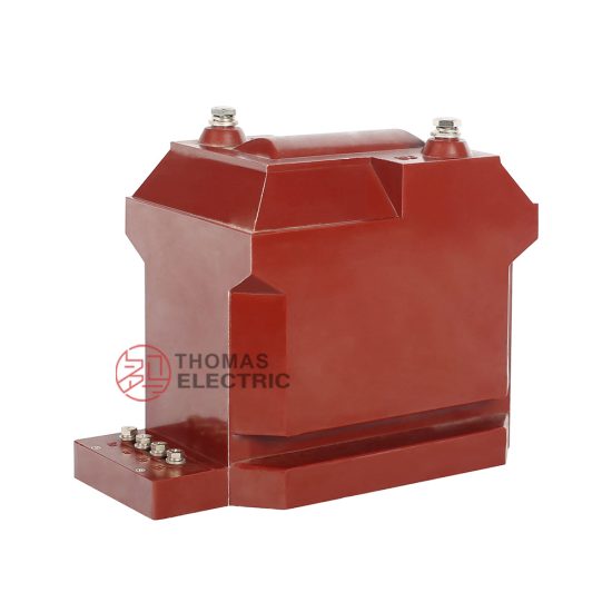
The RZL-10 is a single-phase, cast-resin insulated voltage transformer (VT) engineered for reliable operation in 11 kV medium-voltage (MV) distribution systems per IEC standards, equivalent to legacy 10 kV domestic networks. Designed in strict accordance with IEC 61869-3 and GB/T 20840.3, this instrument transformer provides high-accuracy voltage scaling for metering, protection relaying, and monitoring functions in utility substations, industrial facilities, and renewable energy interconnection points.
Operating Principle of Cast-Resin Insulation
Cast-resin insulation in the RZL-10 employs vacuum pressure impregnation (VPI) epoxy technology, where the primary and secondary windings—wound on grain-oriented electrical steel (GOES) cores—are fully encapsulated in a homogeneous, void-free epoxy matrix under controlled vacuum and pressure conditions. This process eliminates air pockets that could lead to partial discharges, ensuring dielectric integrity even under transient overvoltages. The resin system exhibits excellent thermal conductivity (0.2–0.3 W/m·K), enabling efficient heat dissipation during continuous operation at rated load. Unlike oil-filled units, the solid dielectric requires no maintenance, poses no fire hazard, and resists environmental contaminants such as dust, moisture, and salt fog—making it ideal for both indoor switchgear and outdoor pole-mounted installations. The coefficient of thermal expansion is closely matched to copper and steel components, minimizing mechanical stress during thermal cycling between –40°C and +70°C ambient conditions.
Advantages Over Oil-Immersed Designs
Compared to traditional oil-immersed VTs, the RZL-10’s cast-resin construction offers significant operational and safety benefits. First, it eliminates the risk of oil leakage, which can cause environmental contamination and fire hazards in confined spaces like urban substations or industrial plants. Second, the solid insulation provides superior resistance to partial discharge inception voltages (PDIV > 1.2 × Um/√3), enhancing long-term reliability. Third, the compact physical footprint—typically 30% smaller than equivalent oil units—reduces space requirements in switchgear cubicles. Additionally, cast-resin VTs exhibit lower dielectric losses (tan δ < 0.005 at 50 Hz), contributing to improved efficiency and reduced heating under harmonic-rich conditions common in modern grids with power electronics. Finally, the absence of breathing mechanisms prevents moisture ingress, eliminating the need for silica gel breathers and associated maintenance.
Typical Applications Overview
The RZL-10 is deployed across diverse MV infrastructure where precision, safety, and longevity are critical. Primary use cases include revenue metering at utility feeders, where Class 0.2 or 0.5 accuracy ensures billing compliance; protection coordination in radial or looped networks using overvoltage, undervoltage, or directional earth-fault relays; and synchro-check functions during generator synchronization in distributed generation sites. Its robust design also supports integration into smart grid architectures, providing stable secondary signals for phasor measurement units (PMUs) and digital substations compliant with IEC 61850. With a standard service life exceeding 25 years under normal operating conditions, the RZL-10 represents a lifecycle-cost-effective solution for modern power systems transitioning toward higher reliability and automation.
Technical Specifications
The RZL-10 voltage transformer is engineered to deliver consistent performance under defined electrical and environmental parameters. All specifications align with IEC 61869-3:2011 and GB/T 20840.3-2013, ensuring interoperability across global markets.
| Parameter | Value |
|---|---|
| System Voltage (IEC) | 11 kV (Um = 12 kV) |
| Domestic System Voltage | 10 kV |
| Primary Voltage | 11,000 / √3 V (for grounded systems) |
| Secondary Voltage | 100 / √3 V or 100 V (user-selectable) |
| Voltage Ratio | 11,000/√3 : 100/√3 V or 11,000/√3 : 100 V |
| Accuracy Classes | Metering: 0.2, 0.5; Protection: 3P, 6P |
| Rated Output (per burden class) | 10–100 VA (e.g., 30 VA at 0.5 class) |
| Insulation Level (LI/AC) | 75 kV / 28 kV (1.2/50 μs lightning impulse & 1-min power frequency) |
| Core Material | Grain-Oriented Electrical Steel (GOES), 0.27 mm thickness |
| Insulation System | VPI Epoxy Resin, Class F (155°C) |
| Polarity | Reducing Polarity (standard) |
Standard Service Conditions
The RZL-10 is rated for operation under standard service conditions as defined in IEC 61869-3: ambient temperature range of –40°C to +40°C (with 24-hour average ≤ +35°C), relative humidity up to 95% non-condensing, and installation altitude not exceeding 1,000 meters above sea level. For altitudes between 1,000 m and 3,000 m, derating factors apply to the insulation withstand levels per IEC 60071-2. The transformer is suitable for both indoor and outdoor environments when mounted with appropriate IP-rated terminal boxes (typically IP54). It withstands seismic loads up to 0.5g horizontal acceleration, making it suitable for moderate seismic zones. Continuous operation is permitted at 1.2 × rated primary voltage for up to 8 hours without degradation in accuracy or insulation integrity.
Accuracy and Burden Characteristics
Accuracy performance is guaranteed within specified burdens and voltage ranges. For example, a unit rated 0.2 class must maintain ratio error ≤ ±0.2% and phase displacement ≤ ±10 minutes at 80–120% of rated voltage and 25–100% of rated burden. Protection-class VTs (3P/6P) ensure errors remain within ±3% or ±6% respectively under fault conditions (up to 190% of rated voltage). The secondary winding is designed with low leakage reactance (< 0.5 Ω) to minimize voltage drop under dynamic loading. Burden compatibility includes electromagnetic relays, static meters, and modern digital IEDs with input impedances ≥ 10 kΩ.
Typical Applications
The RZL-10 voltage transformer serves as a foundational component in modern MV power systems, enabling accurate measurement and dependable protection across multiple sectors.
Substation Secondary Metering
In utility-owned 11 kV/0.4 kV distribution substations, the RZL-10 provides the scaled secondary voltage required for revenue-grade energy metering. Installed on each incoming and outgoing feeder, it interfaces with Class 0.2S static meters to record kWh, kVArh, and demand data with traceable accuracy. The transformer’s low phase displacement error (< 5 minutes at 0.2 class) ensures precise power factor calculation, critical for tariff structures involving reactive energy penalties. Its immunity to harmonic distortion (tested up to 13th harmonic per IEC 61869-3 Annex C) maintains accuracy in networks with nonlinear loads such as variable-frequency drives or LED lighting. In ring-main units (RMUs), the compact RZL-10 fits within limited bay dimensions while supporting remote reading via AMI systems.
Industrial Power Distribution
Large manufacturing plants operating on 10 kV internal distribution networks rely on the RZL-10 for both process monitoring and protective relaying. In steel mills or chemical plants, where arc furnaces or rectifiers generate significant harmonics, the GOES core and optimized winding geometry minimize saturation and heating. The VT supplies signals to multifunction relays (e.g., over/undervoltage, loss-of-potential detection) that safeguard sensitive machinery. Its fire-resistant resin construction meets stringent industrial safety codes (e.g., NFPA 70E), eliminating oil-related hazards in hazardous locations. Furthermore, the RZL-10 supports power quality analysis by providing clean secondary waveforms to PQ monitors, aiding in compliance with EN 50160 or IEEE 519 standards.
Renewable Energy Integration
Solar photovoltaic (PV) farms and wind turbine clusters connecting to 11 kV collector grids utilize the RZL-10 for grid-code compliance monitoring and anti-islanding protection. During cloud transients or wind gusts, rapid voltage fluctuations occur; the VT’s fast response time (< 10 ms rise time) ensures relays detect abnormal conditions within required clearing times. It enables synchro-check relays to verify voltage magnitude, frequency, and phase angle before closing the grid-tie breaker, preventing out-of-phase connections. In microgrids with battery storage, the RZL-10 supports state-of-charge estimation and islanding detection algorithms by delivering stable secondary signals even during bidirectional power flow.
Rural and Suburban Distribution Networks
In remote or semi-urban areas with extended 10 kV feeders, the RZL-10 is mounted on poles or pad-mounted transformers to provide localized voltage sensing. Its weather-resistant housing withstands UV exposure, rain, and temperature extremes without degradation. Utilities deploy these VTs for automated voltage regulation—feeding data to line regulators or capacitor banks to maintain customer voltage within ±5% of nominal. For outage management, the VT’s secondary signal confirms de-energization before crew dispatch, enhancing worker safety. Its 25+ year service life reduces replacement frequency in hard-to-access locations, lowering total cost of ownership.
Compliance with International Standards
The RZL-10 is certified to meet the rigorous requirements of both international and Chinese national standards, ensuring global acceptance and interoperability.
IEC 61869-3 Compliance Details
IEC 61869-3:2011 (“Instrument transformers – Part 3: Additional requirements for inductive voltage transformers”) defines performance, testing, and marking criteria for VTs. The RZL-10 complies fully with all mandatory clauses, including accuracy verification under defined burdens, temperature rise limits (≤ 60 K for resin above ambient), and short-circuit withstand capability (withstanding 100 × rated current for 1 second without damage). Dielectric tests include 1-minute AC withstand at 28 kV and lightning impulse at 75 kV (positive and negative polarity, 15 shots each). Partial discharge measurements are conducted at 1.2 × Um/√3, with levels maintained below 10 pC—well under the 20 pC limit for resin-insulated VTs. Markings include rated voltage factor (1.2 for continuous, 1.9 for 8 hours), accuracy class, and vector group (single-phase: I/I).
GB/T 20840.3 Alignment
GB/T 20840.3-2013 is the Chinese national adoption of IEC 61869-3, with minor editorial differences but identical technical content. The RZL-10 is dual-marked for both standards, facilitating deployment in China’s State Grid and Southern Grid infrastructure. Key alignment points include identical insulation levels (LI/AC = 75/28 kV for 10 kV systems), burden definitions (VA ratings), and accuracy class structure. Chinese certification bodies (e.g., CEPREI) perform type tests mirroring IEC protocols, ensuring equivalence. Notably, GB/T 20840.3 explicitly references the use of GOES cores and epoxy resin systems, matching the RZL-10’s construction.
Key Differences Between IEC and Domestic Interpretations
While technically harmonized, practical differences exist in application. IEC 61869-3 uses 11 kV as the nominal system voltage (Um = 12 kV), whereas Chinese practice often refers to “10 kV” systems—though insulation levels remain identical. Some legacy Chinese utilities specify secondary voltages of 100 V line-to-line instead of 100/√3 V phase-to-neutral, requiring ratio adjustment during ordering. Additionally, Chinese grid codes may impose stricter harmonic immunity requirements (e.g., THD tolerance up to 8%), which the RZL-10 meets through core lamination optimization. Certification documentation must therefore reflect both IEC and GB markings to satisfy procurement authorities in different regions.
On-Site Testing Procedures
Post-installation verification ensures the RZL-10 operates within specification before energization. All tests follow IEC 61869-3 Annex D and IEEE C57.13 guidelines.
Insulation Resistance Test
Using a 2,500 V DC megohmmeter, measure insulation resistance between primary winding and ground, secondary winding and ground, and primary-to-secondary. Acceptance criteria: ≥ 1,000 MΩ at 20°C. Correct for temperature using the formula RT2 = RT1 × 2(T1–T2)/10. Low readings indicate moisture ingress or resin cracking—requiring drying or replacement. Perform before and after high-voltage tests to detect insulation degradation.
Turns Ratio Test
Apply a low-voltage AC source (50–100 V) to the primary and measure secondary voltage with a calibrated voltmeter. Calculate actual ratio and compare to nameplate. Tolerance: ±0.2% for 0.2 class, ±0.5% for 0.5 class. Use a dedicated ratio tester (e.g., Omicron CT Analyzer) for automated comparison. Deviations beyond tolerance suggest winding faults or incorrect tap selection.
Polarity Test
Verify reducing polarity using the DC kick method: briefly apply 6–12 V DC to primary (H1 positive, H2 negative); observe momentary deflection on a center-zero galvanometer connected to secondary (X1 to positive terminal). A forward kick confirms correct polarity. Incorrect polarity causes 180° phase reversal, leading to metering errors or relay misoperation in differential or directional schemes.
Power Frequency Withstand Voltage Test
Apply 28 kV RMS at 50 Hz between primary and ground (secondary shorted and grounded) for 1 minute. Monitor for flashover, excessive leakage current (> 1 mA), or audible discharge. This validates insulation integrity after transport and installation stresses. Do not exceed test duration to avoid unnecessary aging.
Open-Circuit Characteristic Test
With secondary open, gradually increase primary voltage from 20% to 120% of rated value while recording excitation current. Plot volts vs. amps: knee point should be ≥ 150% of rated voltage. Excessive magnetizing current at rated voltage indicates core saturation due to manufacturing defect or prior overvoltage damage. This test is critical for protection-class VTs used in earth-fault detection.
Preventive Maintenance Guide
Although cast-resin VTs require minimal maintenance, periodic checks extend service life and prevent unexpected failures.
Periodic Inspection Protocol
Conduct annual visual and thermographic inspections. Check for surface tracking, cracks, or discoloration on the resin housing—indicative of partial discharge activity. Use an infrared camera to detect abnormal heating at terminals (ΔT > 15 K above ambient suggests loose connections). Clean dirt and salt deposits with deionized water and soft brush; avoid solvents that may degrade resin. Verify terminal tightness to 12 N·m torque. Record secondary voltage under load; deviations > 1% from baseline warrant further testing.
Maintenance Intervals and Fault Diagnosis
Every 5 years, perform full electrical tests (insulation resistance, ratio, polarity). Replace if insulation resistance drops below 500 MΩ or ratio error exceeds twice the accuracy class limit. Common failure modes include: (1) terminal corrosion causing open-circuit—diagnosed by infinite secondary voltage; (2) core lamination shorts—detected by elevated no-load losses; (3) resin delamination—identified via ultrasonic testing or PD mapping. Maintain a logbook with test results to track degradation trends.
| Interval | Action |
|---|---|
| Annually | Visual inspection, IR scan, terminal check |
| Every 5 Years | Full electrical tests (IR, ratio, polarity, OC curve) |
| After Fault | Dielectric and ratio tests before re-energization |
Conclusion
The RZL-10 11kV cast-resin voltage transformer represents a benchmark in medium-voltage instrumentation, combining IEC 61869-3-certified accuracy with the inherent safety and longevity of epoxy-resin technology. Its GOES core and VPI encapsulation deliver exceptional stability under harmonic distortion, thermal cycling, and transient overvoltages—critical for modern grids integrating renewables and power electronics. By eliminating fire risks and maintenance burdens associated with oil-filled designs, the RZL-10 enhances substation safety while supporting revenue-grade metering and dependable protection coordination. Compliance with both IEC and GB standards ensures global applicability, from urban utility substations to remote industrial sites. With a proven service life of 25–30 years under standard operating conditions, it offers a compelling lifecycle cost advantage. Engineers specifying the RZL-10 gain a technically robust, future-ready solution that aligns with evolving grid reliability and digitalization mandates, ensuring decades of precise, trouble-free operation in demanding 11 kV (10 kV) networks.