Article Content
11kV Cast-Resin Voltage Transformer SJW-3 for Metering and Protection – IEC 61869-3 Standard
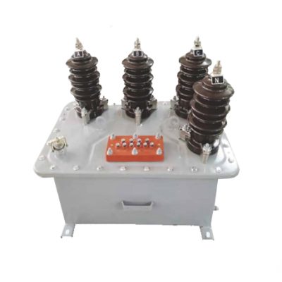
Introduction to the SJW-3 Voltage Transformer
The SJW-3 is a precision-engineered, cast-resin insulated voltage transformer (VT) designed for reliable operation in medium-voltage (MV) networks rated at 11 kV (IEC standard), equivalent to the domestic 10 kV system voltage commonly used in China and select regional grids. Unlike legacy oil-immersed designs, the SJW-3 employs vacuum pressure impregnation (VPI) epoxy resin technology to encapsulate its magnetic core and windings, delivering superior dielectric strength, environmental resilience, and maintenance-free operation over a service life exceeding 25 years. This section details the operating principles, comparative advantages, and typical deployment scenarios of the SJW-3 VT.
Operating Principle of Cast-Resin Insulation
Cast-resin insulation in the SJW-3 VT utilizes a two-component cycloaliphatic epoxy resin system applied under vacuum and pressure to fully impregnate the primary and secondary windings wound around a grain-oriented electrical steel (GOES) core. This process eliminates air voids and moisture ingress pathways, resulting in a monolithic solid dielectric structure with a relative permittivity (εr) of approximately 4.0 and volume resistivity exceeding 1×10¹⁴ Ω·cm at 20°C. The absence of liquid insulation eliminates risks associated with oil leakage, fire hazards, and environmental contamination. Furthermore, the thermal class of the resin system is F (155°C), enabling continuous operation at ambient temperatures up to 40°C with a hot-spot temperature rise limited to 100 K above ambient per IEC 61869-3. The mechanical rigidity of the cast body also provides excellent resistance to short-circuit electromagnetic forces, ensuring long-term dimensional stability of winding geometry and consistent ratio accuracy.
Advantages Over Oil-Immersed Designs
Compared to traditional oil-filled VTs, the SJW-3 offers multiple technical and operational benefits. First, it requires no periodic oil sampling, dielectric testing, or conservator tank maintenance, significantly reducing lifecycle costs. Second, its solid insulation enables compact physical dimensions—typically 30–40% smaller than equivalent oil-immersed units—facilitating installation in space-constrained ring main units (RMUs) and prefabricated substations. Third, the absence of flammable oil enhances safety in indoor and urban environments, aligning with modern fire codes such as IEC 61439. Additionally, cast-resin VTs exhibit lower partial discharge levels (<5 pC at 1.2 Um/√3) and superior performance under polluted or humid conditions due to hydrophobic surface properties and creepage distance optimization (≥25 mm/kV for pollution degree III). Finally, the SJW-3 demonstrates excellent transient response characteristics with a defined knee-point voltage and low remanence, critical for accurate fault detection in protection relaying schemes.
Typical Applications Overview
The SJW-3 is deployed across diverse MV infrastructure where high metrological integrity and system reliability are paramount. Primary applications include secondary metering in utility-owned 11 kV/0.1 kV substations, voltage sensing for overvoltage and undervoltage protection relays in industrial switchgear, synchronization monitoring in distributed generation interconnection points (e.g., solar PV plants), and voltage reference provision in automated distribution feeder systems. Its robust design supports both indoor and outdoor mounting, with optional silicone rubber sheds for enhanced pollution performance in coastal or industrial zones. The transformer’s dual secondary windings—one dedicated to 0.5-class metering and another to 3P-class protection—enable simultaneous compliance with revenue metering accuracy requirements and fast-acting relay coordination curves without cross-interference.
Technical Specifications
The SJW-3 voltage transformer adheres to stringent electrical and mechanical parameters defined by IEC 61869-3 and GB/T 20840.3. Below is a comprehensive specification table followed by environmental and operational constraints.
| Parameter | Value |
|---|---|
| System Voltage (Un) | 11 kV (IEC) / 10 kV (Domestic) |
| Maximum System Voltage (Um) | 12 kV |
| Voltage Ratio | 11,000/√3 V : 100/√3 V (standard); optional 11,000/√3 : 100/3 V for residual voltage |
| Accuracy Class (Metering) | 0.2, 0.5 (per IEC 61869-3) |
| Accuracy Class (Protection) | 3P, 6P |
| Rated Output (Burden) | 30 VA (0.5 class), 50 VA (3P class) at cos φ = 0.8 lag |
| Insulation Level (LI/AC) | 75 kV (lightning impulse) / 28 kV (power frequency, 1 min) |
| Partial Discharge | <5 pC at 1.2 × Um/√3 |
| Core Material | Grain-Oriented Electrical Steel (GOES), 0.27 mm thickness |
| Insulation System | VPI Cycloaliphatic Epoxy Resin, Thermal Class F |
| Weight | Approx. 45 kg |
| Dimensions (H×W×D) | 680 mm × 280 mm × 220 mm |
Standard Service Conditions
The SJW-3 is rated for operation under standard environmental conditions as defined in IEC 60060-1 and IEC 61869-3. Ambient temperature range: –25°C to +40°C, with a 24-hour average not exceeding +35°C. Relative humidity: up to 100% at +25°C, including condensation. Altitude: ≤1,000 m above sea level; for installations above 1,000 m, dielectric withstand voltages must be derated by 1% per 100 m increment beyond 1,000 m. The transformer is suitable for both indoor (pollution degree II) and outdoor (pollution degree III) use when equipped with extended creepage sheds. Seismic performance meets Zone 2 requirements per IEC 60068-2-57 (horizontal acceleration 0.25g). No forced ventilation is required under normal load conditions.
Electrical Performance Tolerances
Voltage error and phase displacement must remain within IEC 61869-3 limits across the full burden range (25–100% of rated VA) and frequency band (48–52 Hz). For a 0.5-class metering winding, voltage error shall not exceed ±0.5% and phase displacement ≤±20 minutes at rated voltage and burden. For the 3P protection winding, voltage error is limited to ±3% and phase displacement to ±120 minutes under the same conditions. Ratio tolerance is maintained within ±0.25% of nominal due to precision winding techniques and core annealing processes that minimize hysteresis losses. Temperature rise tests confirm that under continuous 1.2× rated voltage at maximum ambient (40°C), the winding temperature does not exceed 155°C (Class F limit).
Typical Applications
The SJW-3 cast-resin VT serves as a critical interface between high-voltage primary circuits and low-voltage instrumentation, enabling safe, accurate, and reliable system monitoring and control.
Substation Secondary Metering
In 11 kV/0.4 kV distribution substations, the SJW-3 provides the voltage input for revenue-grade kWh meters, demand recorders, and power quality analyzers. Its 0.5-class accuracy ensures compliance with utility billing regulations (e.g., DL/T 448 in China). The transformer is typically mounted on the 11 kV busbar within metal-enclosed switchgear, with secondary leads routed to a metering cabinet via shielded twisted-pair cables to minimize electromagnetic interference. A key advantage in this application is the elimination of oil handling during routine meter calibration, reducing outage time and safety risks.
Industrial Power Distribution
Large manufacturing facilities often operate internal 10/11 kV distribution networks fed from utility tie-lines. Here, the SJW-3 supplies voltage signals to multifunction protection relays (e.g., over/under voltage, directional earth fault) and SCADA RTUs. The dual-winding configuration allows one output to feed a 0.5-class energy management system while the other drives a 3P-class relay with independent burden loading. In environments with high harmonic distortion (e.g., from variable frequency drives), the low-loss GOES core and optimized magnetic circuit minimize saturation effects, preserving waveform fidelity up to the 13th harmonic.
Renewable Energy Integration
Solar photovoltaic (PV) and wind farms frequently connect to the grid at 10/11 kV. The SJW-3 is used at the point of common coupling (PCC) to provide voltage reference for anti-islanding protection, voltage ride-through (VRT) compliance monitoring, and reactive power control. Its fast transient response (dV/dt > 5 kV/μs withstand capability) ensures accurate capture of grid disturbances during fault events. Outdoor-rated versions with UV-stabilized resin and hydrophobic sheds are standard for these applications, resisting degradation from prolonged solar exposure and salt spray in coastal sites.
Rural and Suburban Distribution Networks
In remote or semi-urban areas, pole-mounted or pad-mounted RMUs rely on compact, maintenance-free VTs like the SJW-3 for feeder automation. It enables voltage monitoring for automatic voltage regulators (AVRs) and sectionalizers, supporting smart grid initiatives such as FLISR (Fault Location, Isolation, and Service Restoration). The transformer’s immunity to oil leakage is particularly valuable in regions with limited maintenance access or extreme temperature swings that could compromise gasket seals in oil-filled units. Field data from deployments in Southeast Asia show mean time between failures (MTBF) exceeding 150,000 hours under these conditions.
Compliance with International Standards
The SJW-3 is engineered and tested to meet the rigorous requirements of global and national standards governing instrument transformers.
IEC 61869-3 Certification Details
IEC 61869-3:2011 specifies performance, safety, and testing criteria for inductive voltage transformers. The SJW-3 complies with all mandatory clauses, including insulation coordination (Clause 6), temperature rise limits (Clause 7), accuracy verification (Clause 8), and short-circuit withstand (Clause 9). Type tests performed by accredited laboratories include power frequency withstand (28 kV, 1 min), lightning impulse (75 kV, 1.2/50 μs waveform), partial discharge measurement (<5 pC), and accuracy validation across burden and voltage ranges. Routine tests on every unit include ratio check (±0.25% tolerance), polarity verification, and insulation resistance (>1,000 MΩ at 2,500 V DC). The manufacturer issues a test certificate traceable to national metrology institutes.
Alignment with GB/T 20840.3
GB/T 20840.3-2013 is the Chinese national adoption of IEC 61869-3, with minor editorial differences but identical technical content. The SJW-3 is certified by CQC (China Quality Certification Centre) for domestic market compliance. Key alignment points include identical accuracy classes (0.2, 0.5, 3P, 6P), burden definitions, and insulation levels. However, GB/T 20840.3 explicitly references Chinese climatic conditions (e.g., –40°C cold start for Northeast China), which the SJW-3 accommodates through resin formulation adjustments that maintain flexibility down to –40°C without cracking.
Key Differences Between IEC and Domestic Standards
While technically harmonized, practical differences exist in certification processes and labeling. IEC certification focuses on type-test evidence and factory quality management (ISO 9001), whereas GB/T 20840.3 mandates batch sampling by provincial metrology bureaus for accuracy verification before grid connection. Additionally, Chinese utilities often specify secondary terminal blocks conforming to GB/T 11022 rather than IEC 61869-1 terminal standards, though the SJW-3 offers both options. Despite these administrative variances, the core electrical performance remains consistent, allowing the same SJW-3 unit to serve both export and domestic markets with minimal configuration changes.
On-Site Testing Procedures
Post-installation verification ensures the SJW-3 operates within specified tolerances and maintains system integrity.
Insulation Resistance Test
Using a 2,500 V DC megohmmeter, measure insulation resistance between primary winding and ground, and between primary and secondary windings. Acceptance criterion: ≥1,000 MΩ at 20°C. Correct for temperature using the formula RT2 = RT1 × 2((T1–T2)/10). Values below 500 MΩ indicate moisture ingress or resin degradation and require investigation. Perform before and after dielectric tests to detect insulation damage.
Turns Ratio Test
Apply a low-voltage AC source (50–100 V) to the primary and measure secondary voltage with a calibrated true-RMS meter. Calculate actual ratio and compare to nameplate. Tolerance: ±0.25% for 0.5-class windings. Use a dedicated ratio tester (e.g., Omicron CT Analyzer) for automated comparison. Deviations beyond tolerance suggest winding shorts or incorrect tap selection.
Polarity Test
Verify reducing polarity per IEC 61869-1. Apply a 6–12 V DC pulse to the primary (H1 to H2) and observe secondary voltage polarity (X1 to X2) with an analog voltmeter. A momentary positive deflection confirms correct polarity. Incorrect polarity compromises vector group alignment in three-phase metering and causes relay misoperation.
Power Frequency Withstand Voltage Test
Apply 28 kV RMS at 50 Hz between primary and grounded secondary/core for 1 minute. Use a calibrated test transformer with overcurrent trip set at 10 mA. No flashover or disruptive discharge is permitted. This test validates insulation integrity after transport and installation stresses. Perform only if factory test records are unavailable or after major maintenance.
Open-Circuit Characteristic Test
For VTs, the open-circuit (excitation) test assesses core health. Gradually increase primary voltage from 0 to 1.5× Un/√3 while measuring excitation current. Plot V vs. I curve; compare to factory baseline. A 20% increase in magnetizing current at rated voltage indicates core lamination damage or shorted turns. This test is critical after exposure to severe overvoltages or ferroresonance events.
Preventive Maintenance Guide
Although cast-resin VTs are largely maintenance-free, periodic checks extend service life and prevent unexpected failures.
Annual Visual and Electrical Inspection
Inspect for surface cracks, tracking marks, or UV degradation on the resin housing. Clean sheds with deionized water if contaminated by dust or salt. Check terminal tightness (torque: 15 N·m for M8 bolts). Measure insulation resistance and secondary burden impedance annually. Record trends; a 30% drop in insulation resistance over two years warrants further diagnostics. Verify secondary circuit grounding continuity (<0.1 Ω).
Five-Year Comprehensive Maintenance
Every five years, perform partial discharge measurement using IEC 60270 methods. Acceptable level: <10 pC at 1.2 Um/√3. Re-calibrate accuracy using a portable standard VT and compare against initial test data. Inspect mounting hardware for corrosion, especially in coastal areas. Replace any degraded cable glands or sealing compounds. Update asset management records with new test results.
Maintenance Intervals and Fault Diagnosis
| Interval | Action | Fault Indicators |
|---|---|---|
| Annually | Visual inspection, IR test, terminal check | Cracks, discoloration, IR <500 MΩ |
| 3 Years | Burden verification, polarity recheck | Metering drift, relay false trips |
| 5 Years | PD test, accuracy recalibration | Excitation current ↑20%, ratio error >0.5% |
| As Needed | After fault events or overvoltage | Ferroresonance history, lightning strike |
Common faults include secondary winding open-circuit (causing dangerous overvoltage on primary side) and core saturation due to excessive burden. Always de-energize and ground before maintenance.
Conclusion
The SJW-3 11kV cast-resin voltage transformer represents a mature, field-proven solution for accurate metering and dependable protection in modern medium-voltage power systems. By leveraging VPI epoxy resin insulation and GOES core technology, it eliminates the operational liabilities of oil-immersed alternatives while delivering superior dielectric performance, environmental resilience, and long-term stability. Compliance with IEC 61869-3 and GB/T 20840.3 ensures global interoperability and regulatory acceptance across utility, industrial, and renewable energy sectors. Its dual-winding architecture supports concurrent metering and protection functions without compromise, and rigorous factory and field testing protocols guarantee performance within tight tolerances throughout its 25–30 year design life. As grids evolve toward greater automation and distributed generation, the SJW-3’s compact footprint, maintenance-free operation, and robust transient response make it an indispensable component for reliable voltage sensing in critical infrastructure. Engineers specifying MV instrumentation can confidently deploy the SJW-3 knowing it meets the highest international benchmarks for safety, accuracy, and longevity.
Frequently Asked Questions (FAQ)
Q1: Can the SJW-3 be used in a 10 kV system even though it’s rated for 11 kV?
Yes. The 11 kV rating refers to the IEC standard system voltage (Un = 11 kV, Um = 12 kV), which corresponds to the domestic 10 kV nominal system (where Un = 10 kV, Um = 12 kV). The SJW-3 is fully compatible with 10 kV networks as the maximum system voltage (12 kV) is identical in both standards.
Q2: What is the minimum secondary burden required for the SJW-3 to maintain accuracy?
Per IEC 61869-3, the minimum burden for accuracy class verification is 25% of rated VA. For a 30 VA (0.5 class) winding, the minimum connected burden should be ≥7.5 VA. Operating below this may increase ratio and phase errors beyond class limits.
Q3: Is the SJW-3 suitable for outdoor installation without additional housing?
Yes. The standard SJW-3 features an IP54-rated cast-resin body with optional extended creepage sheds for pollution degree III environments. It withstands rain, dust, and UV exposure without degradation. However, in heavy industrial or coastal zones, supplementary silicone coating is recommended.
Q4: How does the SJW-3 handle ferroresonance?
The SJW-3 incorporates design features to mitigate ferroresonance, including core cross-section optimization and controlled saturation characteristics. However, like all VTs, it remains susceptible under single-phase switching conditions with capacitive loads. Damping resistors (typically 100–500 Ω, 500 W) should be connected across the open delta or residual winding in unearthed or high-impedance earthed systems.
Q5: Can the secondary windings be paralleled to increase burden capacity?
No. Paralleling metering and protection windings is prohibited as they have different accuracy characteristics and internal impedances, leading to circulating currents, inaccurate metering, and potential overheating. Each winding must feed its designated load independently.
Q6: What is the expected service life of the SJW-3 under normal operating conditions?
With proper installation and adherence to maintenance guidelines, the SJW-3 has a design life of 25–30 years. Accelerated aging studies per IEC 60085 confirm that thermal, electrical, and environmental stresses do not significantly degrade the epoxy resin or GOES core within this period.