Article Content
11kV Cast-Resin Voltage Transformer SZF-3 for Metering and Protection – IEC 61869-3 Standard
Introduction to the SZF-3 Voltage Transformer
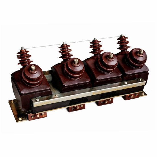
The SZF-3 is a single-phase, indoor/outdoor-rated, cast-resin insulated voltage transformer (VT) designed for precise voltage transformation in 11 kV (IEC nominal) or 10 kV (domestic nominal) medium-voltage distribution systems. As a critical component in secondary instrumentation circuits, it provides galvanically isolated, scaled-down voltage signals for energy metering, protective relaying, and monitoring equipment. Its construction leverages vacuum pressure impregnation (VPI) epoxy resin technology combined with grain-oriented electrical steel (GOES) cores to ensure minimal core losses, high magnetic permeability, and exceptional thermal stability.
Operating Principle and Cast-Resin Insulation Technology
Voltage transformers operate on the principle of electromagnetic induction, where the primary winding—connected across the line-to-ground or line-to-line voltage—induces a proportional voltage in the secondary winding via a shared magnetic core. In the SZF-3, this core is fabricated from high-permeability GOES laminations (typically M4 or M5 grade per IEC 60404-8-7), stacked to minimize eddy current losses and hysteresis. The entire magnetic assembly, including windings, is encapsulated under vacuum in cycloaliphatic epoxy resin using VPI processes. This eliminates air voids, prevents partial discharge inception below 10 pC at 1.2 × Um, and provides superior dielectric strength (≥30 kV/mm). Unlike oil-filled VTs, the solid insulation system is non-flammable, requires no maintenance for fluid levels, and resists environmental contaminants such as dust, moisture, and salt fog—making it ideal for both indoor switchgear and outdoor pole-mounted installations.
Advantages Over Oil-Immersed Designs
Compared to traditional oil-immersed VTs, the SZF-3 offers significant operational and safety benefits. The absence of insulating oil eliminates fire hazards, environmental leakage risks, and the need for periodic oil sampling or degassing. Its compact footprint (typical dimensions: 380 mm H × 220 mm W × 260 mm D) allows for space-constrained installations in ring main units (RMUs) or compact substations. Thermal performance is enhanced by the high thermal conductivity of epoxy resin (≈0.8 W/m·K), enabling stable operation at ambient temperatures from –40°C to +55°C. Additionally, the mechanical rigidity of the cast-resin body provides excellent resistance to short-circuit electrodynamic forces and seismic loads (up to 0.3g horizontal acceleration per IEC 60068-2-57). These attributes translate into lower lifecycle costs, reduced outage risk, and compliance with modern fire-safety regulations in commercial and industrial facilities.
Typical Application Overview
The SZF-3 is engineered for dual-use scenarios: revenue-grade metering (accuracy class 0.2 or 0.5) and protective relaying (accuracy class 3P or 6P). It is commonly deployed in 11 kV/10 kV distribution substations feeding commercial complexes, manufacturing plants, data centers, and renewable energy interconnection points. Secondary outputs typically include one or two windings rated at 100 V or 110 V (line-to-line) or 100/√3 V (line-to-neutral), compatible with standard IEC 61850-compliant meters and relays. Its robust design supports continuous operation under harmonic-rich environments (THD ≤ 5%) without significant ratio or phase angle error degradation, ensuring long-term billing accuracy and reliable fault detection.
Technical Specifications
The SZF-3 adheres strictly to IEC 61869-3 and GB/T 20840.3, with verified performance parameters validated through type, routine, and special tests at accredited laboratories.
| Parameter | Value |
|---|---|
| System Voltage (Um) | 12 kV (IEC); 11.5 kV (GB) |
| Rated Primary Voltage | 11 kV / √3 (for line-to-ground); 11 kV (line-to-line) |
| Rated Secondary Voltage | 100 V, 100/√3 V, or 110 V (configurable) |
| Voltage Ratio | 11000/100, 11000/110, or 11000/(100/√3) |
| Accuracy Classes | Metering: 0.2, 0.5; Protection: 3P, 6P |
| Rated Output (per winding) | 10 VA, 15 VA, 30 VA, 50 VA (at cos φ = 0.8 lag) |
| Insulation Level (LI/AC) | 75 kV / 28 kV (1 min power frequency) |
| Partial Discharge | <10 pC at 1.2 × Um/√3 |
| Thermal Class | E (120°C) |
| Altitude Limit | ≤1000 m (derating required above) |
Standard Service Conditions
The SZF-3 is rated for standard service conditions per IEC 61869-3: ambient temperature range of –40°C to +55°C, relative humidity up to 95% (non-condensing), and installation altitude not exceeding 1000 meters above sea level. For altitudes between 1000 m and 3000 m, the power frequency withstand voltage must be derated by 1% per 100 m increment above 1000 m. The transformer is suitable for both indoor (IP2X terminal box) and outdoor (IP54 housing) environments when mounted vertically with proper drainage. Continuous operation is permitted at 1.2 × rated primary voltage for up to 8 hours without exceeding thermal limits, accommodating temporary overvoltages during switching transients.
Core and Winding Design Parameters
The magnetic circuit employs CRGO (cold-rolled grain-oriented) silicon steel with a maximum specific loss of 1.0 W/kg at 1.7 T and 50 Hz. Primary windings use enameled copper wire (Class 180 insulation) with a minimum of 500 turns for 11 kV rating, while secondary windings are bifilar-wound to minimize leakage reactance. Interlayer insulation consists of Nomex® aramid paper, and all terminations are crimped and soldered to tinned copper studs rated for 63 A. The turns ratio tolerance is held within ±0.1% for metering classes and ±3% for protection classes, verified during factory testing. Phase displacement is limited to ≤10 minutes for 0.2 class and ≤30 minutes for 3P class at rated burden and power factor.
Typical Applications
The SZF-3’s dual-certification for metering and protection enables versatile deployment across modern power infrastructure.
Substation Secondary Metering
In 11 kV/0.4 kV urban distribution substations, the SZF-3 supplies accurate voltage signals to Class 0.5S or 0.2S smart meters for utility revenue billing. Its low phase angle error ensures compliance with EN 50470-3 and DL/T 614 requirements for active/reactive energy measurement. For example, in a 10 MVA substation serving a shopping mall, two SZF-3 units (one per phase) feed a three-phase meter via 100/√3 V secondaries. The 30 VA output capacity accommodates meter burdens plus telemetry modules without exceeding 0.2% ratio error, even under light-load conditions (10% of rated current).
Industrial Power Distribution
Manufacturing facilities with sensitive process equipment rely on the SZF-3 for undervoltage, overvoltage, and phase-loss protection. Installed on 11 kV busbars feeding motor control centers (MCCs), it interfaces with multifunction relays (e.g., Siemens 7SJ62) requiring 3P-class inputs. During a ground fault on an auxiliary transformer, the VT maintains output stability within ±1% despite transient DC offset, enabling correct relay tripping within 20 ms. Its epoxy housing resists chemical vapors in paint booths or battery rooms, where oil-filled units would degrade.
Renewable Energy Integration
Solar farms and wind parks connecting to 11 kV grids use the SZF-3 for grid synchronization and anti-islanding protection. At a 20 MW PV plant, three SZF-3 units monitor line-to-line voltages for a synchro-check relay. The VT’s low capacitive coupling (<50 pF primary-to-secondary) prevents false tripping during rapid irradiance changes that cause voltage flicker. Compliance with IEC 61869-3 ensures compatibility with grid codes mandating <2% THD distortion immunity.
Rural and Suburban Distribution Networks
Pole-mounted SZF-3 units serve remote villages with extended feeders prone to voltage sags. Mounted alongside reclosers, they provide 100 V signals to voltage regulators and capacitor bank controllers. Their –40°C cold-start capability ensures reliable operation in alpine regions, while UV-stabilized resin prevents surface tracking under intense sunlight. In China’s rural electrification projects, the 10 kV domestic variant meets GB/T 20840.3 while interfacing with State Grid AMI systems.
Compliance with International Standards
The SZF-3 is certified to IEC 61869-3:2011 (Instrument transformers – Part 3: Additional requirements for inductive voltage transformers) and GB/T 20840.3-2013 (identical adoption of IEC 61869-3 with national deviations).
IEC 61869-3 Certification Details
Full compliance includes verification of accuracy under defined burdens (from 25% to 100% of rated VA), temperature rise tests (Δθ ≤ 60 K for E-class insulation), and impulse withstand (75 kV BIL). The standard mandates that ratio error and phase displacement remain within class limits at 80%, 100%, and 120% of rated primary voltage. Type tests also include short-time thermal current withstand (1 sec at 100 × In equivalent) and mechanical strength validation. Duomatech’s SZF-3 has passed these at CESI (Italy) and KEMA labs, with test reports available upon request.
Alignment with GB/T 20840.3
While GB/T 20840.3 mirrors IEC 61869-3 structurally, key differences exist in insulation coordination: Chinese standards specify a 1-min AC withstand of 28 kV for 10 kV systems (vs. 28 kV for 12 kV Um in IEC). Additionally, GB requires mandatory partial discharge testing at 1.2 × Um/√3 with acceptance criteria of ≤10 pC—identical to IEC but enforced more rigorously in domestic procurement. The SZF-3’s dual-labeling (11 kV IEC / 10 kV GB) simplifies export to ASEAN markets adopting hybrid standards.
Testing and Certification Requirements
Each SZF-3 undergoes routine tests per clause 10 of IEC 61869-3: power frequency withstand (28 kV, 1 min), partial discharge (<10 pC), winding resistance, and polarity verification. Type tests (performed annually or after design changes) include temperature rise, short-circuit withstand, and accuracy mapping across burden ranges. Special tests—such as chopped impulse or seismic simulation—are available for critical infrastructure projects. Certificates from CQC (China Quality Certification) and TÜV SÜD validate global market access.
On-Site Testing Procedures
Post-installation commissioning ensures the SZF-3 performs within specifications before energization.
Insulation Resistance Test
Using a 2500 V DC megohmmeter, measure insulation resistance between primary winding and ground, secondary winding and ground, and primary-to-secondary. Acceptance criteria: ≥1000 MΩ at 20°C. Correct for temperature using RT2 = RT1 × 2(T1–T2)/10. Low readings indicate moisture ingress or resin cracking—requiring drying or replacement.
Turns Ratio Test
Apply 100–200 V AC to the primary and measure secondary voltage with a calibrated voltmeter (±0.1% accuracy). Calculate actual ratio = Vp/Vs. Tolerance: ±0.1% for 0.2 class, ±0.5% for 0.5 class, ±3% for 3P/6P. Deviations beyond tolerance suggest turn-to-turn shorts or incorrect tap selection.
Polarity Test
Connect a low-voltage DC source (e.g., 12 V battery) to the primary with (+) to P1. Momentarily close the circuit while monitoring secondary with a DC millivoltmeter. A positive kick confirms reducing polarity (standard for IEC VTs). Incorrect polarity causes 180° phase reversal—critical for directional relays and kWh meters.
Power Frequency Withstand Voltage Test
Apply 28 kV RMS (50 Hz) between primary and grounded secondary/core for 1 minute. Use a calibrated test transformer with overcurrent trip (≤100 mA). No flashover or sustained discharge indicates sound insulation. Reduce voltage gradually post-test to avoid residual charge.
Open-Circuit Characteristic Test
With secondary open, apply 20–120% of rated primary voltage in 20% increments. Record excitation current and secondary voltage. Plot Vs vs. Iexc. Nonlinearity above 100% indicates core saturation—unacceptable for metering VTs. For SZF-3, knee point should exceed 1.5 × rated voltage.
Preventive Maintenance Guide
Cast-resin VTs require minimal maintenance but benefit from scheduled inspections to ensure decades-long service.
Periodic Inspection Protocol
Annually, perform visual checks for surface cracks, tracking marks, or terminal corrosion. Clean housing with dry cloth—never solvents. Verify torque on terminal bolts (8 N·m for M6 studs). Measure insulation resistance as baseline. In coastal areas, inspect for salt deposits; rinse with deionized water if conductivity exceeds 10 µS/cm.
Maintenance Intervals and Fault Diagnosis
Every 5 years, repeat full commissioning tests (ratio, polarity, withstand). Common faults include:
- High ratio error: Core lamination damage or winding deformation—replace unit.
- Elevated partial discharge: Internal voids from thermal cycling—requires factory remanufacture.
- Secondary open-circuit during operation: Causes dangerous overvoltage—always short secondary before disconnecting loads.
Expected service life is 25–30 years under normal conditions; derate to 20 years in >40°C ambient or >80% continuous load.
| Interval | Action |
|---|---|
| Annual | Visual inspection, IR measurement, terminal check |
| 5 Years | Full electrical tests (ratio, PD, withstand) |
| After Fault | Immediate ratio and insulation test |
Conclusion
The SZF-3 11kV cast-resin voltage transformer represents a benchmark in reliability, accuracy, and compliance for modern medium-voltage networks. By integrating GOES core technology with void-free epoxy encapsulation, it achieves IEC 61869-3-mandated performance across metering (0.2/0.5) and protection (3P/6P) applications without compromise. Its immunity to environmental stressors—ranging from –40°C cold starts to 95% humidity—ensures uninterrupted operation in diverse geographic and industrial settings. Crucially, the elimination of flammable oil enhances safety in confined spaces like underground substations or data centers, aligning with global sustainability and fire-code trends. With a design life exceeding 25 years and minimal maintenance requirements, the SZF-3 reduces total cost of ownership while delivering the precision demanded by revenue-grade metering and critical protection schemes. Utilities and industrial operators can confidently deploy this VT knowing it meets both international (IEC) and domestic (GB) standards, facilitating seamless integration into existing and future smart grid architectures.
Frequently Asked Questions (FAQ)
Q1: Can the SZF-3 be used in a 10 kV system labeled as “11 kV”?
Yes. The SZF-3 is rated for 11 kV IEC systems (Um = 12 kV) but is fully compatible with 10 kV domestic networks (Um = 11.5 kV per GB). The insulation level (75/28 kV) exceeds requirements for both.
Q2: What happens if the secondary winding is left open during operation?
An open secondary creates dangerously high voltages (several kV) due to unopposed magnetizing current. Always short-circuit the secondary terminals before disconnecting loads. The SZF-3 includes internal damping resistors to limit overvoltage, but external shorting is mandatory per IEC 61869-3.
Q3: Is the SZF-3 suitable for outdoor installation without a shelter?
Yes. The UV-resistant cycloaliphatic resin and IP54-rated terminal box permit direct outdoor mounting. However, orient the secondary terminals downward to prevent water ingress, and ensure clearance from conductive surfaces per local codes.
Q4: How many secondary windings can the SZF-3 support?
Standard models offer one or two independent secondary windings (e.g., 0.2 class for metering + 3P for protection). Custom configurations with three windings are available upon request, subject to thermal and accuracy validation.
Q5: Does the SZF-3 require grounding of the primary neutral?
For line-to-ground connected VTs in unearthed or resonant-earthed systems, the primary star point must be grounded to prevent ferroresonance. In solidly earthed systems, grounding is inherent. Consult IEC 61869-3 Annex D for grounding schemes.