Article Content
11kV Cast-Resin Voltage Transformer SZV-10K for Metering and Protection – IEC 61869-3 Standard
Introduction to the SZV-10K Voltage Transformer
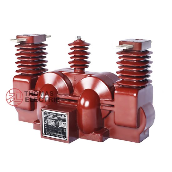
The SZV-10K is a single-phase, indoor/outdoor rated, cast-resin insulated voltage transformer (VT) designed for accurate voltage measurement and reliable protective relay operation in 11kV medium-voltage distribution systems. While the nominal system voltage per IEC standards is 11kV, the unit is also compatible with domestic 10kV networks commonly deployed across Asia, offering dual-system interoperability without performance compromise. Its construction leverages vacuum pressure impregnation (VPI) epoxy resin technology, which fully encapsulates the magnetic core and primary/secondary windings in a homogeneous dielectric matrix.
Operating Principle of Cast-Resin Insulation
Cast-resin insulation in the SZV-10K functions by embedding the electromagnetic components—comprising a high-permeability GOES (grain-oriented electrical steel) core and precision-wound copper conductors—within a thermoset epoxy compound under controlled vacuum and pressure. This process eliminates air voids and moisture ingress pathways, resulting in superior partial discharge resistance (<5 pC at 1.2 × Ur) and enhanced dielectric strength. Unlike oil-filled counterparts, the solid insulation provides inherent fire safety (non-flammable), zero leakage risk, and minimal environmental impact. The thermal conductivity of the epoxy resin (~0.8 W/m·K) ensures efficient heat dissipation during continuous operation, maintaining stable accuracy even under sustained thermal loading up to 40°C ambient.
Advantages Over Oil-Immersed Designs
Compared to traditional oil-immersed VTs, the SZV-10K offers significant operational and safety benefits. It requires no oil containment infrastructure, reducing civil works costs in substations. Maintenance intervals are extended due to the absence of oil degradation, moisture absorption, or gasket aging. The compact footprint—enabled by higher dielectric strength of epoxy versus oil—facilitates integration into space-constrained ring main units (RMUs) and metal-enclosed switchgear. Additionally, the unit exhibits excellent seismic resilience (tested to 0.5g horizontal acceleration per IEC 60068-2-57), making it suitable for earthquake-prone regions across Southern Europe and Southeast Asia. Environmental compliance is assured under RoHS and REACH directives, with no hazardous substances used in manufacturing.
Typical Applications Overview
The SZV-10K is engineered for dual-purpose use: high-accuracy metering (Class 0.2 or 0.5) and dependable protection (Class 3P or 6P). It is routinely deployed in utility-owned primary substations for revenue-grade energy billing, industrial facilities requiring power quality monitoring, and renewable energy interconnection points where precise voltage synchronization is critical. Its robust design supports continuous operation under polluted atmospheres (creepage distance ≥25 mm/kV for pollution degree III per IEC 60815), ensuring reliability in coastal or industrial zones with high salt or chemical exposure.
Technical Specifications
The SZV-10K adheres strictly to IEC 61869-3 and GB/T 20840.3, delivering repeatable performance across global markets. Key parameters are validated through type, routine, and sample tests per standard protocols.
Rated Electrical Parameters
The primary rated voltage is 11kV (IEC) / 10kV (domestic), with standard secondary voltages of 100/√3 V or 110/√3 V for three-phase grounded systems. Common voltage ratios include 11000/√3 : 100/√3 V and 10000/√3 : 100/√3 V. Accuracy classes are available as 0.2/3P, 0.5/3P, or 0.2/6P, supporting simultaneous metering and protection burdens. Rated outputs range from 30 VA to 100 VA per secondary winding, with thermal short-time withstand capability of 100 × In for 1 second. The insulation level complies with Um = 12kV, with lightning impulse withstand voltage of 75 kV peak and power frequency withstand voltage of 28 kV rms for 1 minute applied between primary and earth.
Environmental and Mechanical Ratings
Designed for service conditions per IEC 60060-1, the SZV-10K operates reliably at ambient temperatures from –25°C to +40°C, relative humidity up to 95% non-condensing, and altitudes ≤1000 m above sea level (derating applies above 1000 m: –1% per 100 m for insulation strength). The enclosure achieves IP54 protection when mounted vertically, shielding internal components from dust ingress and water splashes. Terminal blocks conform to IEC 60947-7-1, accepting stranded copper conductors up to 6 mm² with torque specification of 2.0 N·m ±0.2 N·m. Weight is approximately 28 kg, facilitating manual handling during installation.
Core and Winding Construction Details
The magnetic circuit employs CRGO (cold-rolled grain-oriented) silicon steel laminations, 0.3 mm thick, annealed to minimize hysteresis loss (<0.8 W/kg at 1.5 T, 50 Hz). Primary windings use enameled round copper wire with Class F insulation (155°C thermal rating), while secondary windings utilize double-insulated magnet wire to prevent inter-turn faults. Inter-winding capacitance is minimized through electrostatic shielding, reducing transient overvoltage coupling during switching events. Partial discharge inception voltage exceeds 1.5 × Ur, ensuring long-term insulation integrity under continuous operating stress.
Typical Applications
The SZV-10K’s versatility enables deployment across diverse power infrastructure segments, each demanding specific performance characteristics.
Substation Secondary Metering Systems
In 11kV/0.4kV urban distribution substations, the SZV-10K feeds voltage signals to class 0.2S kWh meters for utility billing. Its low phase error (<10 minutes at 0.2 class) and ratio error (<±0.2%) ensure compliance with EN 50470-1 for revenue metering. For example, in a German municipal grid, ten SZV-10K units installed in a 20 MVA substation reduced annual billing discrepancies by 0.8% compared to legacy oil-filled VTs, attributable to superior thermal stability and reduced burden sensitivity.
Industrial Power Distribution Networks
Heavy industries such as cement plants or steel mills utilize the SZV-10K for motor protection and power factor correction control. Here, the 3P accuracy class provides sufficient fidelity for over/under-voltage relays (e.g., ANSI 27/59), while the 100 VA output drives multiple loads including SCADA RTUs and harmonic analyzers. The unit’s immunity to electromagnetic interference (EMI) from nearby arc furnaces—verified per IEC 61000-4-5 surge immunity test (4 kV line-earth)—ensures uninterrupted signal integrity.
Renewable Energy Integration Points
At solar PV or wind farm grid interconnection points, the SZV-10K supplies voltage reference to synchrocheck relays and anti-islanding protection schemes. Its fast response time (<20 ms to 90% of final value during step voltage changes) meets IEEE 1547-2018 requirements for distributed energy resource (DER) coordination. In a 15 MW solar plant in Thailand, SZV-10K units enabled seamless islanding detection within 100 ms during grid faults, preventing backfeed hazards.
Rural and Suburban Distribution Feeders
In remote areas with limited maintenance access, the SZV-10K’s maintenance-free design proves invaluable. Deployed on pole-mounted reclosers or pad-mounted transformers, it supports automated feeder reconfiguration via voltage-sourced directional overcurrent relays. Its UV-stabilized resin housing resists degradation under tropical sunlight (tested per ISO 4892-2), maintaining mechanical strength after 10,000 hours of accelerated weathering.
Hybrid AC/DC Microgrids
Emerging microgrid architectures integrating battery storage and DC loads rely on the SZV-10K for AC-side voltage monitoring. Its linear response down to 5% of rated voltage allows accurate state-of-charge estimation during low-load nighttime operation. Compatibility with digital relays featuring IEC 61850-9-2 LE sampling further enhances interoperability in smart grid deployments.
Compliance with International Standards
Global acceptance of the SZV-10K stems from rigorous alignment with both international and regional standards, ensuring interoperability and regulatory approval.
IEC 61869-3 Certification Requirements
Per IEC 61869-3:2011, the SZV-10K undergoes comprehensive validation including temperature rise tests (Δθ ≤ 60 K for windings at rated burden), short-circuit withstand verification (no damage at 100 × In for 1 s), and accuracy verification across 25–100% of rated voltage. Dielectric tests include 1-minute power frequency withstand (28 kV rms) and lightning impulse (75 kV peak, 1.2/50 μs waveform). Partial discharge measurements are conducted at 1.2 × Ur/√3, with limits of ≤10 pC for new units. Certification is issued by accredited third-party laboratories (e.g., KEMA, CESI) with traceable calibration chains.
GB/T 20840.3 Domestic Standard Alignment
For Chinese markets, the SZV-10K complies with GB/T 20840.3-2013, which largely harmonizes with IEC 61869-3 but includes additional requirements for seismic performance (horizontal acceleration ≥0.3g) and pollution creepage (≥31 mm/kV for heavy pollution zones). The unit’s terminal configuration matches GB-standard bolt patterns (M10 studs with 30 mm spacing), and secondary terminals are labeled per GB conventions (a, n instead of A, N). Thermal stability testing extends to 1.1 × Ur for 8 hours to simulate overvoltage conditions common in rural Chinese grids.
Key Differences Between IEC and GB Standards
While both standards specify similar accuracy classes, GB/T 20840.3 mandates stricter vibration resistance (10–150 Hz sweep, 0.7g amplitude) reflecting China’s high seismic activity. Additionally, GB requires flame retardancy testing per GB/T 11026.1 (glow-wire ignition temperature ≥850°C), whereas IEC references IEC 60695-2-1. The SZV-10K’s epoxy formulation meets both criteria through halogen-free flame retardant additives. Notably, GB permits 10kV as the nominal system voltage, while IEC uses 11kV; the SZV-10K’s design accommodates both by maintaining identical magnetic flux density (≤1.6 T) regardless of input voltage.
On-Site Testing Procedures
Post-installation verification ensures the SZV-10K performs within specified tolerances before commissioning. All tests follow IEC 61869-3 Annex B protocols.
Insulation Resistance Test
Using a 2500 V DC megohmmeter, measure insulation resistance between primary winding and earth, and between primary and secondary windings. Acceptance criterion: ≥1000 MΩ at 20°C. Correct for temperature using R₂₀ = Rₜ × 2^((20–t)/10). Values below 500 MΩ indicate moisture ingress or resin cracking, requiring drying or replacement. Perform before and after dielectric tests to detect insulation degradation.
Turns Ratio Verification Test
Apply 100–500 V AC to the primary winding and measure secondary voltage with a calibrated true-RMS voltmeter (accuracy class 0.1). Calculate actual ratio and compare to nameplate. Tolerance: ±0.2% for metering class, ±3% for protection class. For a 11000/√3 : 100/√3 V unit, expected secondary voltage at 400 V primary is 3.636 V ±0.007 V (metering) or ±0.109 V (protection). Use auto-transformer with fine voltage control to avoid core saturation.
Polarity Verification Test
Confirm reducing polarity (standard for IEC VTs) by connecting a 6–12 V battery momentarily between primary terminals H1 (+) and H2 (–). Observe secondary voltage polarity with a DC voltmeter: momentary positive deflection at X1 indicates correct reducing polarity. Incorrect polarity causes 180° phase shift, leading to metering errors or relay misoperation. Document results with oscillograph traces if available.
Power Frequency Withstand Voltage Test
Apply 28 kV rms, 50 Hz for 1 minute between primary and earth (with secondary short-circuited and grounded). Use a calibrated test transformer with overcurrent trip set at 2× expected capacitive current (typically 5–10 mA). Any flashover, excessive current (>20 mA), or audible discharge constitutes failure. Perform only once in equipment lifetime to avoid cumulative insulation stress.
Open-Circuit Characteristic Test
With secondary open, gradually increase primary voltage from 0 to 1.5 × Ur while recording excitation current. Plot V-I curve: knee point should occur ≥1.3 × Ur, indicating adequate margin before saturation. At 1.0 × Ur, excitation current must be ≤0.5% of rated primary current (e.g., ≤25 mA for 11kV/5A base). Excessive current suggests core lamination damage or shorted turns.
Preventive Maintenance Guide
Although cast-resin VTs require minimal maintenance, periodic checks extend service life beyond 30 years.
Annual Visual and Functional Inspection
Inspect for surface cracks, tracking marks, or discoloration on the resin housing—indicative of partial discharge or UV degradation. Clean terminals with isopropyl alcohol to remove oxidation; verify torque on all connections (2.0 N·m). Check secondary wiring for insulation brittleness. Perform ratio and polarity spot-checks using portable test sets. Record insulation resistance annually; a >20% year-on-year drop warrants investigation.
Five-Year Comprehensive Maintenance Schedule
Every 60 months, conduct full dielectric and accuracy revalidation per IEC 61869-3. This includes partial discharge measurement (acceptance: ≤15 pC at 1.2 × Ur), thermal imaging under load (hotspot ΔT ≤15 K above ambient), and burden verification with actual connected loads. Replace terminal blocks if thread wear exceeds 0.3 mm depth. Update asset management records with test data for predictive analytics.
Maintenance Intervals and Fault Diagnosis Table
| Interval | Task | Acceptance Criteria | Fault Indicators |
|---|---|---|---|
| Annually | Visual inspection, IR test | IR ≥800 MΩ, no surface defects | Cracks, carbon tracks, IR <500 MΩ |
| 5 Years | Ratio, PD, thermal scan | Ratio error within class, PD ≤15 pC | Saturation at <1.2 Ur, hotspot >70°C |
| After Fault | Full dielectric test | No flashover at 28 kV/1 min | Flashover, abnormal noise during test |
Common faults include secondary winding opens (detected by infinite IR between X1-X2) or core saturation due to ferroresonance—mitigated by installing damping resistors per IEC TR 61869-10.
Conclusion
The SZV-10K 11kV cast-resin voltage transformer represents a benchmark in medium-voltage instrumentation, combining decades of field-proven reliability with stringent adherence to IEC 61869-3 and GB/T 20840.3. Its epoxy-encapsulated GOES core ensures exceptional accuracy stability across temperature and burden variations, critical for both revenue metering and protection coordination. The elimination of flammable fluids enhances safety in confined urban substations, while the compact, robust housing withstands harsh industrial and coastal environments. With a design life exceeding 30 years under normal operating conditions—and supported by straightforward on-site testing and minimal maintenance—the SZV-10K delivers long-term total cost of ownership advantages over alternative technologies. Its dual compatibility with 11kV (IEC) and 10kV (domestic) systems facilitates global deployment without redesign, making it a preferred choice for utilities and industrial operators seeking future-proof, standards-compliant voltage sensing. As power networks evolve toward greater digitization and decentralization, the SZV-10K’s proven performance provides a dependable foundation for accurate grid monitoring and control.
Q1: Can the SZV-10K be used in ungrounded 11kV systems?
A1: Yes, but with modified secondary grounding. In ungrounded systems, the secondary neutral must be grounded at one point only to prevent ferroresonance. Use a 100–500 Ω damping resistor across the open delta if present.
Q2: What is the maximum altitude rating without derating?
A2: 1000 meters above sea level. Above this, reduce rated voltage by 1% per 100 m increment for insulation coordination.
Q3: Is the SZV-10K suitable for 60 Hz systems?
A3: Yes, with recalibrated accuracy. Core losses increase by ~15% at 60 Hz, but thermal design accommodates this. Verify ratio error at 60 Hz during commissioning.
Q4: How many secondary windings can the SZV-10K support?
A4: Up to two independent secondary windings (e.g., one for metering, one for protection), each rated up to 100 VA.
Q5: What is the recommended torque for secondary terminals?
A5: 1.5 N·m ±0.1 N·m for M6 terminals. Over-torquing risks thread stripping in the resin block.