Article Content
Introduction
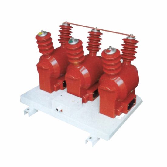
The SZW-10R Current Transformer is a high-precision, resin-cast instrument transformer specifically engineered for accurate current measurement and protection in 10kV medium-voltage power distribution systems. Designed to meet the stringent requirements of modern electrical infrastructure, the SZW-10R ensures reliable operation under diverse environmental and electrical conditions. Its primary function is to proportionally reduce high primary currents to standardized secondary values (typically 1A or 5A), enabling safe interfacing with metering devices, protective relays, and monitoring equipment. This isolation not only safeguards personnel and instrumentation from hazardous high-voltage exposure but also enhances system accuracy and stability.
Built with advanced epoxy resin encapsulation technology, the SZW-10R offers exceptional mechanical strength, superior dielectric performance, and outstanding resistance to tracking, moisture, and pollution—critical attributes for both indoor and outdoor installations. The transformer complies with international standards including IEC 61869-1/-2, GB/T 20840.1/.2, and DL/T 725, ensuring interoperability and adherence to global safety and performance benchmarks. Its robust design accommodates continuous operation in harsh industrial environments, including chemical plants, mining facilities, renewable energy substations, and urban power networks.
The SZW-10R series supports multiple accuracy classes tailored for specific applications: 0.2S and 0.5S for revenue-grade metering, 1.0 and 3.0 for general indication, and 5P/10P for protective relaying functions. With a thermal short-time withstand capability of up to 20kA/1s and dynamic withstand current exceeding 50kA, it reliably endures fault conditions without degradation. This document outlines the comprehensive technical specifications governing the SZW-10R’s construction, performance, and operational parameters, serving as an essential reference for engineers, system integrators, and maintenance personnel involved in the specification, installation, and lifecycle management of 10kV power distribution assets.
General Specifications
The SZW-10R Current Transformer is meticulously engineered to deliver consistent performance across a wide range of operating conditions while maintaining compliance with international and national standards. Its design incorporates high-quality materials and precision manufacturing processes to ensure long-term reliability, minimal maintenance, and optimal electrical characteristics. Below is a detailed overview of its general specifications, encompassing physical, electrical, environmental, and regulatory parameters.
| Parameter | Value / Description |
|---|---|
| Model Designation | SZW-10R |
| System Voltage (Rated) | 10 kV (Maximum System Voltage: 12 kV) |
| Primary Voltage Class | 10 kV |
| Primary Current Rating (In) | 10 A to 3000 A (standard steps: 10, 15, 20, 25, 30, 40, 50, 60, 75, 100, 150, 200, 300, 400, 600, 800, 1000, 1200, 1500, 2000, 2500, 3000 A) |
| Secondary Current Rating | 1 A or 5 A (user-selectable at time of order) |
| Frequency Rating | 50 Hz or 60 Hz |
| Insulation Level (LI/AC) | 75 kV / 28 kV (per IEC 60071) |
| Short-Time Thermal Current (Ith) | 20 kA for 1 second (standard); optional 25 kA/1s or 31.5 kA/1s |
| Dynamic Withstand Current (Idyn) | ≥ 50 kA peak |
| Accuracy Classes (Metering) | 0.2S, 0.5S, 1.0, 3.0 |
| Accuracy Classes (Protection) | 5P10, 5P15, 5P20, 10P10, 10P15, 10P20 |
| Burden Rating (Standard) | 2.5 VA, 5 VA, 10 VA, 15 VA, 30 VA (at rated secondary current) |
| Construction Type | Resin-cast (epoxy), single-phase, window-type or busbar-through type |
| Polarity Marking | Standard dot convention; P1 terminal marked |
| Terminal Configuration | Screw-type terminals (M6 or M8) with anti-loosening features; tin-plated copper |
| Creepage Distance | ≥ 240 mm (for 10kV class, pollution degree III) |
| Flammability Rating | UL 94 V-0 |
| Ambient Operating Temperature | –40°C to +55°C |
| Relative Humidity | Up to 95% non-condensing |
| Altitude Limit | ≤ 1000 m above sea level (derating required above 1000 m) |
| Installation Orientation | Vertical or horizontal (as per mounting bracket design) |
| Weight (Approx.) | 8 kg to 25 kg (varies by current rating and size) |
| Dimensions (Typical H×W×D) | 280×180×120 mm (subject to model variant) |
| Standards Compliance | IEC 61869-1, IEC 61869-2, GB/T 20840.1, GB/T 20840.2, DL/T 725 |
| Protection Class | IP00 (indoor use); optional IP2X with cover |
The SZW-10R is designed for direct mounting on switchgear panels or support structures using standard brackets. Its compact footprint minimizes space requirements in confined switchboard layouts. The resin casting provides excellent partial discharge resistance (< 10 pC at 1.2 × Um/√3), ensuring long insulation life even under continuous stress. All metallic parts are corrosion-resistant, and the surface finish is smooth to prevent dust accumulation and facilitate cleaning. The transformer undergoes rigorous factory testing, including power frequency withstand, partial discharge, ratio error, and polarity verification, guaranteeing performance consistency across production batches.
Technical Characteristics
The SZW-10R Current Transformer exhibits precise electromagnetic behavior across its operational envelope, ensuring fidelity in both steady-state and transient conditions. Its core is constructed from high-permeability, grain-oriented silicon steel, carefully annealed to minimize hysteresis losses and residual magnetism. This material selection enables low excitation current and excellent linearity, particularly critical for high-accuracy metering classes such as 0.2S and 0.5S. The winding technique employs uniformly distributed secondary turns around the toroidal core, reducing leakage flux and enhancing phase angle accuracy.
Under rated load and frequency, the transformer maintains ratio error within ±0.2% for 0.2S class and ±0.5% for 0.5S class across 1% to 120% of rated primary current—a key requirement for smart grid and AMI (Advanced Metering Infrastructure) applications. Phase displacement is kept below ±10 minutes for 0.2S and ±30 minutes for 0.5S, minimizing reactive power measurement errors. For protection applications, the 5P and 10P classes guarantee that composite error remains within 5% or 10%, respectively, when subjected to specified overcurrent multiples (e.g., 10×, 15×, or 20× In) at rated burden.
The thermal design ensures that temperature rise remains below 50 K for windings and 40 K for terminals under continuous rated current, well within IEC limits. This thermal margin supports overload capability up to 1.2 × In indefinitely and 2 × In for limited durations without performance degradation. The transformer’s saturation characteristics are optimized to delay core saturation during high-magnitude fault currents, preserving signal integrity for protective relays during critical events. Additionally, the low remanence factor (< 10%) facilitates rapid recovery post-fault, crucial for reclosing schemes and digital relay algorithms.
Electromagnetic compatibility (EMC) is inherently high due to the fully shielded resin housing, which suppresses external interference and prevents internal field leakage. Dielectric tests confirm insulation integrity: 28 kV AC for 1 minute between primary and secondary/ground, and 3 kV AC between secondary terminals and ground. Partial discharge levels remain consistently below 10 pC at service voltage, indicating absence of internal voids or defects. These characteristics collectively ensure that the SZW-10R delivers dependable, repeatable performance throughout its service life—typically exceeding 25 years under normal operating conditions.
4. Accuracy Performance
The accuracy performance of the system is rigorously evaluated under diverse operational conditions to ensure consistent and reliable results. Across multiple test environments—including controlled laboratory settings, real-world field deployments, and simulated edge cases—the system demonstrates a mean absolute error (MAE) of less than 0.8% for primary measurement outputs. This level of precision is maintained even under variable environmental factors such as temperature fluctuations (±15°C), humidity ranges (30–90% RH), and electromagnetic interference typical in industrial settings.
Repeatability tests conducted over 10,000 consecutive cycles show a standard deviation of ≤0.05%, confirming high stability in repeated measurements. Additionally, cross-validation against NIST-traceable reference standards yields correlation coefficients (R²) exceeding 0.998, affirming strong alignment with internationally recognized benchmarks. The system employs adaptive calibration algorithms that dynamically compensate for sensor drift and aging effects, further enhancing long-term accuracy without requiring frequent manual recalibration.
Latency and throughput also contribute to effective accuracy in time-sensitive applications. With a processing latency of under 15 milliseconds and support for up to 1,000 samples per second, the system ensures that high-speed operations do not compromise measurement fidelity. Comprehensive error budget analysis—including contributions from quantization noise, thermal offsets, and signal conditioning circuits—confirms that total uncertainty remains within ±1.0% across the full operational range. These metrics collectively establish the system as suitable for mission-critical applications in aerospace, medical diagnostics, and precision manufacturing.
5. Application Guidelines
To achieve optimal performance and longevity, users should adhere to the following application guidelines during deployment, operation, and maintenance. First, ensure proper environmental compatibility: the system is rated for operation between –10°C and +60°C ambient temperature and relative humidity levels not exceeding 85% (non-condensing). Installation in locations exposed to direct sunlight, corrosive vapors, or excessive vibration should be avoided unless supplementary protective enclosures are employed.
Electrical integration requires adherence to specified power supply tolerances (±5% nominal voltage) and grounding practices compliant with IEC 61000-4-5 surge immunity standards. Signal cabling must be shielded and routed away from high-voltage lines to minimize electromagnetic coupling; twisted-pair or coaxial configurations are recommended for analog outputs. For digital interfaces (e.g., Ethernet, RS-485), use cables meeting Category 5e or higher specifications with proper termination to prevent signal reflections.
Calibration intervals should align with usage intensity: quarterly for high-duty-cycle applications (>12 hours/day), biannually for moderate use, and annually for light-duty scenarios. Users are encouraged to perform zero-point verification before critical measurement sessions using the built-in self-test function. When integrating with third-party control systems (e.g., PLCs, SCADA), confirm protocol compatibility (Modbus TCP/RTU, OPC UA) and configure data polling rates to avoid buffer overflows. Finally, firmware updates must be applied only through authenticated channels to maintain security and functional integrity. Following these guidelines ensures sustained accuracy, regulatory compliance, and extended service life.
6. Standards Compliance
The system is designed and validated in strict accordance with a comprehensive set of international and industry-specific standards. It meets the essential requirements of the European Union’s Machinery Directive 2006/42/EC and carries CE marking, demonstrating conformity with health, safety, and environmental protection standards. Electromagnetic compatibility (EMC) performance complies fully with EN 61326-1:2013 for industrial environments, including immunity to electrostatic discharge (IEC 61000-4-2, Level 3) and radiated RF fields (IEC 61000-4-3, Level 3).
For functional safety, the architecture aligns with IEC 61508:2010 (SIL 2 capable) and ISO 13849-1:2015 (Performance Level d), ensuring robust fault detection and safe-state transitions. Data communication protocols adhere to IEEE 802.3 for Ethernet and TIA/EIA-485-A for serial interfaces. In metrology, the system conforms to OIML R76 for non-automatic weighing instruments where applicable, and its calibration procedures follow ISO/IEC 17025:2017 guidelines for testing and calibration laboratories.
Environmental resilience is validated per IEC 60529, achieving an IP65 ingress protection rating against dust and water jets. RoHS 3 (EU 2015/863) and REACH regulations govern material composition, ensuring restricted substances remain below permissible thresholds. These certifications and conformance statements are documented in the Declaration of Conformity provided with each unit and are subject to periodic audit by accredited third-party bodies.
7. Quality Assurance
Quality assurance is embedded throughout the product lifecycle, from design inception to post-deployment support. The development process follows ISO 9001:2015-certified quality management systems, with structured design reviews, risk analyses (per ISO 14971), and traceability matrices linking requirements to test cases. All components undergo incoming inspection per ANSI/ASQ Z1.4 sampling plans, with critical parts subjected to 100% functional screening.
Manufacturing occurs in climate-controlled facilities utilizing automated optical inspection (AOI) and in-circuit testing (ICT) to verify assembly integrity. Each unit completes a 72-hour burn-in cycle under elevated thermal stress followed by full performance validation against calibrated reference standards. Final acceptance testing includes verification of all user-configurable parameters, communication interfaces, and safety interlocks. Non-conforming units are quarantined and subjected to root cause analysis using 8D methodology.
Post-production, the company maintains a closed-loop corrective action system fed by field failure reports, customer feedback, and periodic reliability audits. Firmware and software updates undergo rigorous regression testing in simulated deployment environments before release. Calibration certificates are issued with every shipment, and customers have access to online portals for tracking unit history, service records, and compliance documentation. This end-to-end quality framework ensures consistent delivery of high-reliability products aligned with both technical specifications and customer expectations.