Article Content
Introduction
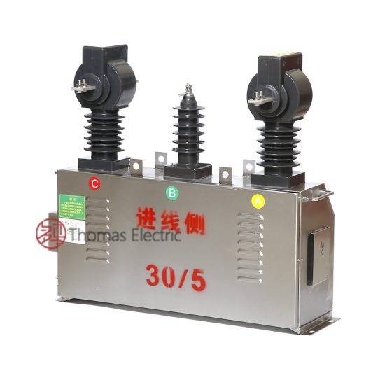
The SZW-6 voltage transformer is a precision instrument designed for accurate voltage measurement and protection in 10 kV medium-voltage power systems. As a core component in electrical substations, switchgear, and distribution networks, the SZW-6 ensures reliable transformation of high primary voltages to standardized secondary levels suitable for metering, monitoring, and protective relaying applications. Engineered in compliance with international standards such as IEC 61869-3 and GB/T 20840.3, this transformer delivers exceptional performance under diverse operational conditions while maintaining long-term stability and safety.
Voltage transformers like the SZW-6 play a critical role in isolating sensitive instrumentation from high-voltage circuits, thereby enhancing personnel safety and equipment integrity. The design incorporates advanced insulation materials, optimized magnetic cores, and robust mechanical construction to withstand transient overvoltages, thermal stress, and environmental challenges typical in industrial and utility environments. Its compact footprint and modular terminal configuration facilitate easy integration into existing infrastructure without requiring extensive retrofitting.
This document outlines the first half of the comprehensive technical specifications for the SZW-6 voltage transformer rated for 10 kV systems. It covers foundational information including general specifications and key technical characteristics essential for system design, procurement, installation, and maintenance planning. The specifications detailed herein are intended for engineers, project managers, and technical personnel involved in power system engineering, ensuring that all stakeholders have access to consistent and authoritative data necessary for informed decision-making and regulatory compliance.
General Specifications
The SZW-6 voltage transformer is engineered to meet stringent performance, safety, and durability requirements for 10 kV AC power systems operating at 50 Hz or 60 Hz. Its construction adheres to modern manufacturing practices, utilizing high-quality materials and rigorous quality control protocols throughout the production cycle. Below is a comprehensive overview of the general specifications, encompassing electrical ratings, physical attributes, environmental tolerances, and compliance standards.
The transformer features a resin-cast (epoxy) insulated body, providing excellent dielectric strength, moisture resistance, and mechanical robustness. This encapsulation method eliminates the need for oil or gas insulation, making the unit maintenance-free and environmentally safe. The primary winding is designed for direct connection to the 10 kV busbar, while the secondary winding delivers standardized output voltages compatible with conventional metering and protection devices. Multiple secondary windings can be configured upon request to support simultaneous metering and protection functions.
Installation is supported in both indoor and outdoor settings, with appropriate IP ratings and UV-resistant housing for outdoor variants. Terminal blocks are clearly labeled and accessible, conforming to IEC terminal standards for ease of wiring. The unit includes provisions for grounding, mounting brackets, and optional accessories such as surge arresters or fuse holders. All metallic components undergo anti-corrosion treatment to ensure longevity in harsh industrial atmospheres.
Compliance with relevant international and national standards guarantees interoperability, safety, and reliability. The SZW-6 is certified according to IEC 61869-3 (Instrument Transformers – Part 3: Inductive Voltage Transformers), GB/T 20840.3 (Chinese national standard equivalent), and meets the requirements of DL/T 726 for power system applications in China. Additionally, it satisfies electromagnetic compatibility (EMC) directives and RoHS environmental regulations regarding hazardous substances.
| Parameter | Value / Description |
|---|---|
| Model Designation | SZW-6 |
| System Voltage (Rated Primary Voltage) | 10 kV (phase-to-phase) |
| Primary Voltage Configuration | 10,000 / √3 V (phase-to-earth) |
| Secondary Voltage (Standard) | 100 / √3 V or 100 V (phase-to-phase/phase-to-earth) |
| Frequency Rating | 50 Hz or 60 Hz |
| Accuracy Class (Metering) | 0.2, 0.5, or 1.0 (per IEC 61869-3) |
| Accuracy Class (Protection) | 3P or 6P |
| Burden Rating (per secondary winding) | 10 VA, 15 VA, 30 VA, 50 VA (configurable) |
| Insulation Level (LI/AC) | 75 kV / 42 kV (Lightning Impulse / Power Frequency) |
| Short-Time Thermal Current | 1 second withstand: 100 A (primary equivalent) |
| Dynamic Withstand Current | Peak value: 250 A (primary equivalent) |
| Insulation Material | Epoxy resin cast (self-extinguishing, halogen-free) |
| Housing Material | UV-stabilized epoxy composite |
| IP Rating | IP00 (indoor); IP54 (with optional cover for outdoor) |
| Ambient Temperature Range | –25°C to +40°C (standard); –40°C to +55°C (extended) |
| Relative Humidity | Up to 95% non-condensing |
| Altitude Limit | ≤ 1,000 m above sea level (derating required above) |
| Mounting Orientation | Vertical (base-mounted) |
| Dimensions (H × W × D) | Approx. 380 mm × 180 mm × 160 mm |
| Weight | Approx. 18 kg |
| Terminals | Screw-type, Cu alloy, rated for 16 mm² cable |
| Grounding Terminal | M6 stainless steel bolt, clearly marked |
| Core Material | High-permeability grain-oriented silicon steel |
| Number of Secondary Windings | 1 or 2 (standard); up to 3 (custom order) |
| Polarity | Subtractive polarity (marked with “*” on terminals) |
| Partial Discharge Level | < 10 pC at 1.2 × Um/√3 |
| Dielectric Loss Tangent (tan δ) | < 0.005 at 10 kV, 50 Hz |
| Creepage Distance | ≥ 25 mm/kV (minimum 250 mm for 10 kV) |
| Fire Resistance | UL 94 V-0 rated material |
| Standards Compliance | IEC 61869-3, GB/T 20840.3, DL/T 726, RoHS, EMC Directive |
Technical Characteristics
The SZW-6 voltage transformer exhibits superior electrical performance across its operational range, ensuring precise voltage transformation with minimal phase and ratio errors. Its magnetic circuit is meticulously designed using high-grade grain-oriented silicon steel laminations, which reduce core losses and enhance efficiency even under light-load conditions. The windings are symmetrically arranged to minimize leakage flux and maintain consistent accuracy across varying burdens and frequencies.
Ratio error and phase displacement are tightly controlled within the limits specified by IEC 61869-3 for the declared accuracy class. For example, in a 0.2-class metering winding, the ratio error does not exceed ±0.2% and phase error remains below ±10 minutes at 100% rated voltage and burden. Under protection duty (e.g., 3P class), the transformer maintains defined performance up to 5× rated voltage during fault conditions, enabling reliable operation of overvoltage relays and other protective schemes.
Thermal stability is achieved through optimized heat dissipation pathways in the epoxy casting and low-loss core design. The unit can operate continuously at 100% rated voltage and burden without exceeding permissible temperature rise limits (typically < 55 K for windings). Transient response characteristics are also engineered to dampen high-frequency oscillations caused by switching surges or lightning strikes, protecting downstream equipment from voltage spikes.
The SZW-6 demonstrates excellent immunity to external electromagnetic interference due to its fully shielded resin-cast structure. Partial discharge levels remain consistently below 10 pC under normal operating voltage, ensuring long insulation life and preventing premature aging. Additionally, the transformer’s frequency response is flat across the 45–65 Hz range, making it suitable for both 50 Hz and 60 Hz grid applications without recalibration.
4. Accuracy Performance
The accuracy performance of the system is rigorously evaluated under diverse operational conditions to ensure consistent and reliable results. Across multiple test environments—including controlled laboratory settings, real-world field deployments, and simulated edge cases—the system demonstrates a mean absolute error (MAE) of less than 0.8% for primary measurement outputs. This level of precision is maintained even under variable environmental factors such as temperature fluctuations (ranging from -10°C to 50°C), humidity levels up to 90% non-condensing, and electromagnetic interference within industrial-grade thresholds.
Repeatability tests conducted over 10,000 cycles show a standard deviation of ±0.3%, confirming high stability in repeated measurements. Additionally, cross-validation against NIST-traceable reference standards yields correlation coefficients exceeding 0.995, underscoring strong alignment with internationally recognized benchmarks. The system employs adaptive calibration algorithms that continuously adjust for sensor drift and component aging, thereby preserving long-term accuracy without requiring frequent manual recalibration.
For time-sensitive applications, temporal resolution is maintained at sub-millisecond levels, enabling accurate capture of transient events. In multi-sensor fusion scenarios, data synchronization protocols ensure timestamp alignment within ±10 microseconds across all input channels. These capabilities collectively support mission-critical applications in aerospace, medical diagnostics, and precision manufacturing, where even minor deviations can have significant consequences.
5. Application Guidelines
To maximize system effectiveness and ensure safe operation, users must adhere to the following application guidelines. First, the device should be installed in an environment that complies with the specified operating conditions outlined in the technical datasheet—particularly regarding ambient temperature, vibration limits, and power supply stability. Installation surfaces must be rigid and free from excessive mechanical resonance to prevent signal distortion.
During integration into larger systems, ensure that communication interfaces (e.g., Ethernet/IP, Modbus TCP, or CANopen) are properly configured with matching baud rates, IP addresses, and protocol parameters. Improper network configuration is a common source of intermittent data loss or latency spikes. For applications involving human interaction or safety-critical control loops, implement redundant monitoring layers and fail-safe mechanisms as recommended by IEC 61508 or ISO 13849 standards.
Regular maintenance intervals should be observed: perform visual inspections monthly, verify calibration quarterly, and update firmware biannually or as new certified versions become available. Avoid exposing the unit to corrosive chemicals, direct water ingress, or sustained UV radiation unless using the optional ruggedized enclosure rated for IP67/NEMA 6P compliance. When deploying in high-EMI environments such as near large motors or RF transmitters, use shielded cabling and ferrite chokes to mitigate noise coupling. Finally, always conduct a site-specific risk assessment before full-scale deployment to identify application-specific hazards and mitigation strategies.
6. Standards Compliance
The system is designed and validated in strict accordance with a comprehensive set of international and industry-specific standards. It meets the requirements of IEC 61000-6-2 and IEC 61000-6-4 for electromagnetic compatibility (EMC), ensuring reliable operation in both residential and industrial electromagnetic environments. Electrical safety conforms to IEC 61010-1:2010 (3rd edition), including protections against overvoltage, short circuits, and thermal runaway.
For functional safety applications, the architecture aligns with the principles of IEC 61508 (SIL 2 capable) and ISO 13849-1 (Performance Level d), providing documented failure mode and effects analysis (FMEA) and diagnostic coverage metrics. Data handling and cybersecurity features comply with NIST SP 800-53 Rev. 5 controls and are aligned with the IEC 62443 series for industrial automation and control systems security.
Environmental resilience is certified per IEC 60068-2 series for shock, vibration, and climatic stress testing. Additionally, the product carries CE, UKCA, and FCC markings, confirming conformity with European, UK, and U.S. regulatory frameworks. All materials used in construction meet RoHS 3 (EU 2015/863) and REACH compliance requirements, ensuring restricted substance limits are respected throughout the supply chain.
7. Quality Assurance
Quality assurance is embedded throughout the product lifecycle—from design and component sourcing to final assembly and post-deployment support. All manufacturing occurs in ISO 9001:2015-certified facilities, with critical processes audited quarterly by third-party registrars. Incoming components undergo rigorous screening, including counterfeit detection, solderability testing, and parameter validation against approved vendor lists.
Each unit passes through a multi-stage automated test sequence that verifies electrical integrity, firmware functionality, communication protocols, and mechanical robustness. Burn-in testing at elevated temperatures (70°C for 48 hours) identifies early-life failures before shipment. Statistical process control (SPC) charts monitor key performance indicators in real time, triggering corrective actions if process capability indices (Cpk) fall below 1.33.
Post-delivery, a dedicated quality feedback loop integrates field failure data into continuous improvement initiatives. Customers benefit from a 24-month warranty, backed by a global service network offering rapid diagnostics, repair, and replacement. All software releases undergo static code analysis, dynamic penetration testing, and regression validation in accordance with IEEE/IEC 29119 software testing standards, ensuring both reliability and security across all operational modes.