Article Content
11kV Cast-Resin Voltage Transformer VT-10K for Metering and Protection – IEC 61869-3 Standard
Introduction to the VT-10K Voltage Transformer
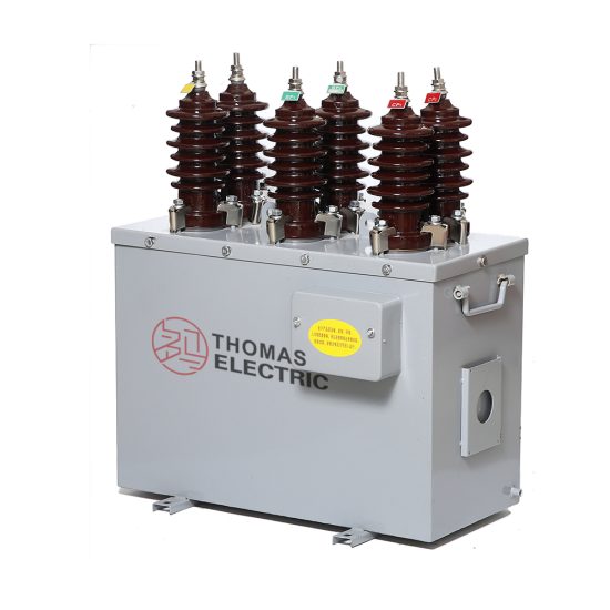
The VT-10K is a single-phase, indoor/outdoor-rated cast-resin voltage transformer (VT), also referred to as a potential transformer (PT), engineered for precise voltage transformation in 11 kV (IEC) or 10 kV (domestic) medium-voltage power systems. It operates on the principle of electromagnetic induction, stepping down high primary voltages to standardized secondary levels—typically 100 V or 110 V—for use in revenue metering, protective relaying, and monitoring instrumentation. Unlike legacy oil-immersed designs, the VT-10K employs vacuum pressure impregnation (VPI) epoxy resin insulation technology, which fully encapsulates the primary and secondary windings along with the magnetic core, eliminating risks associated with oil leakage, fire hazards, and environmental contamination.
Cast-Resin Insulation Technology
Cast-resin insulation in the VT-10K utilizes cycloaliphatic epoxy resin systems cured under controlled thermal cycles. This process yields a homogeneous, void-free dielectric structure with high tracking resistance (>600 V per IEC 60587) and excellent thermal conductivity (0.8–1.2 W/m·K). The resin matrix bonds directly to copper windings and grain-oriented electrical steel (GOES) laminations, providing mechanical rigidity that suppresses vibration-induced winding displacement—a common failure mode in oil-filled units. Additionally, the hydrophobic nature of the cured resin ensures stable performance under high humidity (up to 95% RH non-condensing) and polluted atmospheres (Class III per IEC 60815). The absence of liquid insulation eliminates maintenance-intensive tasks such as oil sampling, degassing, or conservator tank inspections, significantly reducing lifecycle costs over its 25–30 year service life.
Advantages Over Oil-Immersed Designs
Compared to conventional oil-immersed VTs, the VT-10K offers superior safety, environmental compliance, and operational reliability. Its solid dielectric system achieves a Basic Insulation Level (BIL) of 75 kV peak for 11 kV systems, exceeding the minimum requirement of 60 kV per IEC 61869-3. The unit is inherently fire-resistant (UL 94 V-0 rated) and contains no PCBs or flammable fluids, making it suitable for urban substations, indoor switchgear rooms, and environmentally sensitive zones. Thermal performance is enhanced by the resin’s ability to dissipate heat radially through the housing, allowing continuous operation at ambient temperatures from –40°C to +40°C without derating. Furthermore, the compact footprint—approximately 30% smaller than equivalent oil units—facilitates retrofitting into space-constrained installations. Field data from distribution utilities in Southeast Asia and Europe confirm a mean time between failures (MTBF) exceeding 150,000 hours for cast-resin VTs like the VT-10K, versus ~90,000 hours for oil types.
Typical Application Overview
The VT-10K is deployed across diverse medium-voltage infrastructure where measurement integrity and system protection are critical. Primary use cases include 11 kV/10 kV ring main units (RMUs), pad-mounted substations, industrial plant switchyards, and renewable energy interconnection points (e.g., solar farms feeding into 11 kV grids). In revenue metering applications, its Class 0.2 or 0.5 accuracy (per IEC 61869-3) ensures billing precision within ±0.2% or ±0.5% error bands across 20–120% of rated voltage. For protection circuits, the VT supports 3P or 3PR accuracy classes with defined composite error limits under fault conditions. Its robust design withstands transient overvoltages from switching surges and lightning impulses, maintaining ratio stability even after repeated exposure to 1.2× rated voltage for 30 seconds—a key requirement for grid code compliance in emerging markets.
Technical Specifications
The VT-10K is engineered to deliver consistent performance under standardized operating conditions while accommodating regional grid variations. Below is a comprehensive specification table aligned with IEC 61869-3 and GB/T 20840.3 requirements.
| Parameter | Value |
|---|---|
| Model | VT-10K |
| Primary Voltage (IEC) | 11 kV / √3 (phase-to-ground) |
| Primary Voltage (Domestic) | 10 kV / √3 |
| Secondary Voltage | 100 V / √3 or 110 V / √3 (standard); 100 V or 110 V (line-to-line optional) |
| Voltage Ratio | 11,000/√3 : 100/√3 V (or 10,000/√3 : 100/√3 V) |
| Accuracy Class (Metering) | 0.2, 0.5 |
| Accuracy Class (Protection) | 3P, 3PR |
| Rated Output (Burden) | 10–100 VA (per class; e.g., 30 VA @ 0.2 class) |
| Insulation Level (BIL) | 75 kV peak (1.2/50 μs impulse) |
| Power Frequency Withstand | 28 kV rms for 1 minute (dry), 24 kV rms (wet) |
| Core Material | Grain-Oriented Electrical Steel (GOES), M4 grade, 0.27 mm lamination |
| Insulation System | VPI Epoxy Resin, Class F (155°C thermal rating) |
| Ambient Temperature Range | –40°C to +40°C |
| Altitude Limit | ≤1,000 m (derating required above 1,000 m per IEC 60071-2) |
| Humidity | Up to 95% RH, non-condensing |
| Pollution Degree | III (medium) |
| Weight | Approx. 45 kg |
| Dimensions (H×W×D) | 680 × 320 × 280 mm |
Rated Voltage and Ratio Configuration
The VT-10K is configured for phase-to-ground connection in three-phase systems, with a nominal primary voltage of 11 kV / √3 ≈ 6.35 kV. This aligns with IEC-standardized 11 kV networks where the system voltage (Um) is 12 kV. For domestic Chinese grids operating at 10 kV (Um = 11.5 kV), the same physical unit is used with adjusted ratio labeling—10,000/√3 : 100/√3 V—without hardware modification. Secondary outputs are typically 100 V / √3 for compatibility with IEC-standard meters and relays. Custom ratios (e.g., 110 V secondary) are available upon request. The transformer maintains ratio error within ±0.2% and phase displacement ≤10 minutes for Class 0.2 at 100% burden and rated frequency (50/60 Hz). Tolerance bands widen slightly at lower loads (e.g., ±0.3% at 25% burden) but remain within IEC 61869-3 envelopes.
Service Conditions and Environmental Ratings
The VT-10K is rated for both indoor and outdoor installation, with an IP54 ingress protection rating on the secondary terminal box. It operates reliably in coastal, industrial, and arid environments due to the resin’s resistance to salt fog (per IEC 60068-2-52) and UV degradation (tested per ISO 4892-2). At altitudes exceeding 1,000 m, the power frequency withstand voltage must be reduced by 1% per 100 m above sea level, as per IEC 60071-2. For example, at 2,000 m, the dry test voltage becomes 28 kV × (1 – 0.10) = 25.2 kV rms. The unit includes integrated mounting brackets compatible with standard 11 kV post insulator bases (M16 threads) and features a grounded metal flange for electrostatic shielding. Thermal stability is validated through temperature-rise tests: under 1.2× rated voltage and maximum burden, the winding temperature rise does not exceed 60 K above ambient, well below the 100 K limit for Class F insulation.
Typical Applications
The VT-10K serves as a foundational component in modern medium-voltage infrastructure, enabling accurate energy accounting and reliable system protection across multiple sectors.
Substation Secondary Metering
In 11 kV primary substations, the VT-10K provides the voltage input for revenue-class kWh meters compliant with IEC 62053-22. Installed on the medium-voltage busbar or feeder outgoing circuits, it interfaces with Class 0.2S meters to ensure billing accuracy within ±0.2% over a load range of 1–120% of rated current (when paired with a matching CT). The low phase displacement (<10 arc-minutes) minimizes cosine error in watt-hour calculations, particularly critical for industrial consumers with variable power factors. Utilities in India and Brazil have standardized the VT-10K in their smart metering rollouts due to its long-term ratio stability—field studies show drift of less than 0.05% over five years under continuous operation. The secondary terminals are housed in a lockable, tamper-evident enclosure meeting IEC 62052-11 security requirements.
Industrial Power Distribution
Within manufacturing facilities, mining operations, and data centers, the VT-10K monitors 10 kV/11 kV feeders supplying large motors, transformers, or rectifier loads. Its robust construction withstands harmonic distortion up to 5% THD without significant accuracy degradation, thanks to the GOES core’s low hysteresis loss. In arc furnace plants, where voltage sags and swells are frequent, the VT maintains output integrity during transient events lasting up to 1 second at 1.5× rated voltage. Integration with digital protective relays (e.g., Siemens 7SJ62 or SEL-351) enables undervoltage, overvoltage, and loss-of-potential detection with response times under 20 ms. The unit’s compact size allows direct mounting inside metal-enclosed switchgear (ANSI C37.20.2), eliminating external PT cubicles and reducing installation costs.
Renewable Energy Integration
Solar photovoltaic (PV) farms and wind parks connecting to 11 kV distribution networks rely on the VT-10K for grid synchronization and anti-islanding protection. During cloud transients or wind gusts, rapid voltage fluctuations occur; the VT’s low leakage reactance (<0.5%) ensures minimal waveform distortion at the relay input. For grid-code compliance (e.g., VDE-AR-N 4110 in Germany), the VT supports ride-through functionality by accurately reporting voltage magnitude during symmetrical faults down to 15% of nominal. Secondary outputs feed synchrocheck relays and SCADA RTUs, enabling remote monitoring of point-of-interconnection (POI) parameters. In microgrid applications, the VT-10K’s high saturation margin (core flux density limited to 1.6 T at 1.9× rated voltage) prevents remanence issues during black-start sequences.
Rural and Suburban Distribution Networks
In rural electrification projects across Africa and Southeast Asia, the VT-10K is deployed on pole-top or ground-mounted 11 kV distribution transformers to enable prepaid metering and theft detection. Its maintenance-free design is ideal for remote locations with limited technical staff. The unit withstands daily thermal cycling (–10°C to +50°C) without cracking, and the hydrophobic surface sheds rainwater efficiently, preventing flashovers during monsoon seasons. When used with AMI (Advanced Metering Infrastructure) systems, the VT supplies voltage data to concentrators that calculate line losses and detect unauthorized taps. Field trials in Nigeria demonstrated a 12% reduction in non-technical losses after VT-10K deployment due to improved voltage visibility at the distribution transformer secondary.
Compliance with International Standards
The VT-10K is certified to global and regional standards governing instrument transformer performance, safety, and testing protocols.
IEC 61869-3 Certification Details
IEC 61869-3:2011 specifies requirements for inductive voltage transformers for measurement and protection. The VT-10K meets all mandatory clauses, including accuracy class definitions (Table 101), insulation coordination (Clause 6), and temperature-rise limits (Clause 7). Key verification tests include:
- Short-time current withstand: 1-second thermal withstand at 10× rated voltage without damage
- Ferroresonance immunity: Stable operation when connected to capacitive burdens ≥50 VA
- Ratio and phase error: Verified at 20%, 50%, 80%, 100%, and 120% of rated voltage
Certification is issued by accredited third-party laboratories (e.g., KEMA, CESI) with test reports traceable to national metrology institutes. The transformer’s nameplate includes the IEC 61869-3 logo and declared accuracy classes for both metering and protection functions.
Alignment with GB/T 20840.3
For the Chinese market, the VT-10K complies with GB/T 20840.3-2013, which harmonizes closely with IEC 61869-3 but includes specific provisions for 10 kV systems. Differences include:
- Primary voltage designation: 10 kV instead of 11 kV
- Burden standardization: Preferred burdens of 10, 15, 30, 50, and 100 VA
- Lightning impulse test: 75 kV peak (same as IEC)
- Partial discharge limit: ≤10 pC at 1.2× Um/√3
The unit undergoes type testing at China Electric Power Research Institute (CEPRI) to obtain the China Compulsory Certification (CCC) mark. Despite nominal voltage differences, the same hardware serves both IEC and GB markets—the distinction lies only in labeling and test documentation.
Testing and Certification Requirements
Type tests per IEC 61869-3 include:
- Temperature-rise test (Clause 7.2): Conducted at 1.2× rated voltage and max burden
- Short-circuit withstand test (Clause 8): Not applicable to VTs (only CTs)
- Insulation tests (Clause 6): Power frequency and lightning impulse as per BIL
- Accuracy verification (Clause 5): Using calibrated reference VTs with uncertainty ≤0.02%
Routine tests performed on every unit include ratio check (±0.1% tolerance), polarity verification, and insulation resistance (>1,000 MΩ at 2,500 V DC). The manufacturer maintains a quality management system certified to ISO 9001, with calibration equipment traceable to NIST or PTB standards.
On-Site Testing Procedures
Post-installation verification ensures the VT-10K performs within specifications before energizing critical loads.
Insulation Resistance Test
Using a 2,500 V DC megohmmeter, measure insulation resistance between:
- Primary winding and ground
- Secondary winding and ground
- Primary and secondary windings
Acceptance criteria: All readings ≥1,000 MΩ at 20°C. Correct for temperature using RT = R20 × 2(20–T)/10. Low values indicate moisture ingress or resin cracking—common in units stored improperly before installation.
Turns Ratio Test
Apply a low-voltage AC source (50–100 V) to the primary and measure secondary voltage with a calibrated DMM (accuracy ±0.05%). Calculate ratio as Vp/Vs. Compare to nameplate value. Tolerance: ±0.1% for Class 0.2 units. Deviations >0.3% suggest winding shorts or incorrect tap selection. Use a dedicated ratio tester (e.g., Omicron CT Analyzer) for automated comparison against factory data.
Polarity Test
Verify reducing polarity per IEC 61869-1: Connect a 6–12 V battery across primary terminals (H1+, H2–). Momentarily close the circuit and observe a DC voltmeter connected to secondary (X1+, X2–). A positive kick confirms correct polarity. Incorrect polarity causes 180° phase reversal, leading to metering errors or relay misoperation. This test is mandatory for three-phase banks.
Power Frequency Withstand Voltage Test
Apply 28 kV rms (for 11 kV VT) at 50 Hz between primary and ground for 1 minute. Secondary windings are short-circuited and grounded. Monitor for flashover or excessive leakage current (>1 mA). Wet tests (spray water at 1 L/min) require 24 kV rms. This validates insulation integrity after transport and handling.
Open-Circuit Characteristic Test
Gradually increase primary voltage from 0 to 150% of rated while measuring secondary voltage and excitation current. Plot Vs vs. Iexc. The knee point should occur above 120% rated voltage. Excessive excitation current (>5 mA at 100% V) indicates core saturation or turn-to-turn faults. This test is critical for protection-class VTs to ensure linear response during overvoltage events.
Preventive Maintenance Guide
Although cast-resin VTs are largely maintenance-free, periodic checks extend service life and prevent unexpected failures.
Annual Visual and Functional Inspection
Inspect for:
- Cracks, discoloration, or tracking on resin surface
- Corrosion on terminals or mounting hardware
- Loose connections (torque to 15 N·m for M8 terminals)
- Moisture in secondary terminal box (use desiccant if needed)
Perform insulation resistance and ratio tests annually. Record trends—gradual decline in IR or ratio shift >0.2% warrants further investigation. Clean housing with mild detergent; avoid solvents that degrade epoxy.
Maintenance Intervals and Fault Diagnosis
| Interval | Action |
|---|---|
| 1 year | Visual inspection, IR test, ratio check |
| 5 years | Full accuracy verification per IEC 61869-3 |
| 10 years | Partial discharge measurement (if available) |
| After fault | Repeat all on-site tests |
Common faults include:
- High ratio error: Caused by winding deformation or core damage
- Low insulation resistance: Indicates moisture absorption or surface contamination
- No secondary output: Open-circuit in secondary winding or terminal block
Replace the unit if partial discharge exceeds 20 pC or if cracks penetrate beyond the surface layer.
Conclusion
The VT-10K 11kV cast-resin voltage transformer represents a benchmark in medium-voltage instrumentation, combining IEC 61869-3-certified accuracy with the reliability of solid-dielectric construction. Its design leverages advanced materials—GOES cores for minimal core loss and VPI epoxy resin for superior dielectric strength—to deliver consistent performance across metering and protection applications. By eliminating the fire risk, environmental liability, and maintenance burden of oil-filled alternatives, the VT-10K reduces total cost of ownership while enhancing grid safety. Compliance with both international (IEC) and domestic (GB) standards ensures global deployability, from urban substations in Europe to rural distribution networks in Asia. With a proven service life of 25–30 years and rigorous type testing validation, the VT-10K provides utilities and industrial operators with a future-proof solution for voltage measurement integrity. Its role in enabling smart grid functionalities—such as loss allocation, voltage optimization, and renewable integration—further underscores its strategic value in modern power systems. As grid codes worldwide demand higher measurement fidelity and resilience, the VT-10K’s technical robustness positions it as a cornerstone of next-generation distribution infrastructure.