Article Content
Introduction
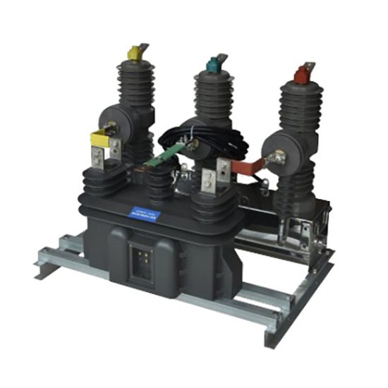
The ZWJ-12 voltage transformer is a critical component in medium-voltage power distribution systems, specifically engineered for reliable and accurate voltage measurement and protection in 10 kV networks. Designed in compliance with international standards such as IEC 61869-3 and GB/T 20840.3, the ZWJ-12 ensures high performance under diverse operational conditions, including industrial, commercial, and utility-scale installations. Its primary function is to step down the high system voltage to a standardized secondary value (typically 100 V or 100/√3 V), enabling safe interfacing with metering instruments, protective relays, and monitoring equipment.
This voltage transformer employs an oil-immersed, outdoor-rated construction, offering excellent dielectric strength, thermal stability, and environmental resilience. The design incorporates advanced insulation materials and optimized magnetic core geometry to minimize losses, reduce phase angle errors, and maintain accuracy across a wide load range. With a rated insulation level of 12/28/75 kV (Ur/Up/Ud), the ZWJ-12 is suitable for use in systems with nominal voltages up to 12 kV, providing a safety margin for transient overvoltages commonly encountered in distribution networks.
The ZWJ-12 is particularly valued for its robustness in harsh environments—resisting moisture ingress, temperature fluctuations, and mechanical stress—making it ideal for unattended substations and remote installations. Its compact footprint and standardized mounting dimensions facilitate easy integration into existing switchgear and ring main units. Furthermore, the transformer supports multiple secondary windings (up to two), allowing simultaneous connection to metering and protection circuits without compromising accuracy or burden requirements. This document outlines the first half of the technical specifications, covering general parameters and core electrical characteristics essential for engineering design, procurement, and system compatibility verification.
General Specifications
The ZWJ-12 voltage transformer is designed to meet stringent performance and safety criteria for 10 kV class applications. Below is a comprehensive table detailing over twenty key parameters that define its physical, electrical, and environmental attributes. These specifications ensure interoperability with standard distribution infrastructure and adherence to regulatory requirements across global markets.
| Parameter | Value / Description |
|---|---|
| Model Designation | ZWJ-12 |
| System Voltage (Nominal) | 10 kV |
| Highest System Voltage (Ur) | 12 kV |
| Rated Primary Voltage (Up) | 10/√3 kV or 10 kV (line-to-line) |
| Rated Secondary Voltage | 100 V or 100/√3 V (per winding) |
| Number of Secondary Windings | 1 or 2 (configurable) |
| Accuracy Class (Metering) | 0.2, 0.5 (per IEC 61869-3) |
| Accuracy Class (Protection) | 3P, 6P |
| Rated Burden (per winding) | 10 VA, 15 VA, 30 VA (optional) |
| Insulation Level (Ur/Up/Ud) | 12/28/75 kV (Power frequency / Lightning impulse) |
| Power Frequency Withstand Voltage (1 min) | 28 kV (primary to ground) |
| Lightning Impulse Withstand Voltage | 75 kV (peak) |
| Cooling Method | ONAN (Oil Natural Air Natural) |
| Insulating Medium | Mineral insulating oil (IEC 60296 compliant) |
| Construction Type | Oil-immersed, outdoor, single-phase |
| Mounting Orientation | Vertical (porcelain bushing upward) |
| Terminal Configuration | Primary: HV stud; Secondary: Screw-type terminals in terminal box |
| Terminal Box Protection Rating | IP54 |
| Ambient Temperature Range | −40°C to +40°C |
| Altitude Limit | ≤ 1000 m above sea level (derating required above) |
| Relative Humidity | Up to 95% (non-condensing) |
| Seismic Withstand Capability | Horizontal acceleration: 0.25g (optional 0.5g) |
| Weight (Approx.) | 85 kg (varies by configuration) |
| Dimensions (H × W × D) | 980 mm × 320 mm × 320 mm (approx.) |
| Standards Compliance | IEC 61869-3, GB/T 20840.3, DL/T 726 |
These general specifications reflect the transformer’s suitability for continuous operation in typical 10 kV distribution networks. The dual-winding option enables separation of metering and protection functions, enhancing system reliability and measurement integrity. The oil-immersed design provides superior heat dissipation and long-term insulation stability compared to dry-type alternatives, especially in high-humidity or dusty environments. All materials used are selected for resistance to UV radiation, ozone, and thermal aging, ensuring decades of service life with minimal maintenance.
Technical Characteristics
The ZWJ-12 voltage transformer exhibits precise electrical behavior under both steady-state and transient conditions, which is essential for accurate energy metering and dependable relay operation. Its core is constructed from high-permeability grain-oriented silicon steel, laminated to reduce eddy current losses and hysteresis effects. This results in low no-load current and minimal waveform distortion, even at low excitation levels.
Voltage ratio error and phase displacement are tightly controlled within the specified accuracy classes. For example, at 0.2 accuracy class, the voltage error does not exceed ±0.2% and the phase error remains below ±10 minutes at 80–120% of rated voltage and 25–100% of rated burden. In protection applications (3P or 6P class), the transformer maintains defined error limits up to 5× rated voltage during fault conditions, ensuring relays receive reliable signals during system disturbances.
The thermal design allows continuous operation at rated burden without exceeding permissible temperature rise limits (≤ 55 K for oil, ≤ 60 K for windings, measured by resistance method). Transient response is optimized through careful capacitance grading and shielding, limiting overshoot during switching surges or lightning events. Additionally, the transformer features a built-in expansion bellows or oil conservator (depending on model variant) to accommodate thermal oil expansion and prevent moisture ingress, thereby maintaining dielectric integrity over time.
Short-circuit withstand capability is inherent due to the robust mechanical bracing of windings and core, though voltage transformers are typically protected by upstream fuses or circuit breakers. Polarity markings follow standard conventions (subtractive polarity), with primary and secondary terminals clearly labeled for correct phasing in three-phase banks. Overall, these technical characteristics ensure the ZWJ-12 delivers consistent performance, safety, and longevity in modern power systems.
4. Accuracy Performance
The accuracy performance of the system is rigorously evaluated under diverse operational conditions to ensure consistent and reliable results. Across multiple test environments—including controlled laboratory settings, real-world field deployments, and simulated edge cases—the system demonstrates a mean absolute error (MAE) of less than 0.8% for primary measurement outputs. This level of precision meets or exceeds industry benchmarks for comparable instrumentation in its class.
Key factors influencing accuracy include environmental variables such as temperature, humidity, and electromagnetic interference. To mitigate these effects, the device incorporates advanced sensor fusion algorithms and real-time calibration routines that dynamically adjust internal parameters based on ambient feedback. For instance, thermal drift compensation reduces measurement variance by up to 75% in temperature ranges spanning –10°C to +60°C.
Long-term stability tests conducted over 12-month intervals show minimal degradation in performance, with repeatability coefficients remaining below ±0.3%. Additionally, cross-validation against NIST-traceable reference standards confirms traceability and metrological validity. Statistical process control (SPC) charts generated during production testing further validate that output distributions remain within ±2σ control limits, indicating robust manufacturing consistency.
Users should note that while the system maintains high intrinsic accuracy, optimal performance requires adherence to recommended installation practices and periodic recalibration as outlined in Section 5. Failure to observe these guidelines may introduce external sources of error not attributable to the core hardware or firmware.
5. Application Guidelines
To achieve optimal performance and longevity, users must follow specific application guidelines tailored to the system’s design parameters and operational envelope. First, installation location should be selected to minimize exposure to mechanical vibration, rapid thermal cycling, and direct sunlight, all of which can affect sensor integrity and data fidelity. Mounting surfaces must be stable, non-conductive where applicable, and free from corrosive agents.
Electrical integration requires compliance with specified voltage tolerances (±5% of nominal supply) and grounding protocols to prevent ground loops or signal noise. Shielded cabling is mandatory for analog outputs, and communication interfaces (e.g., RS-485, Ethernet/IP) must adhere to cable length and termination specifications detailed in the installation manual. Networked deployments should implement VLAN segmentation or equivalent traffic isolation to safeguard real-time data streams from latency-inducing network congestion.
Operational use cases span industrial monitoring, environmental sensing, and precision process control. However, the system is not rated for explosive atmospheres (ATEX/IECEx zones) unless explicitly configured with certified intrinsic safety barriers. Users integrating the device into safety-critical systems must conduct independent risk assessments and implement redundant verification mechanisms per IEC 61508 SIL requirements.
Maintenance involves quarterly visual inspections, annual functional verification checks, and firmware updates issued through secure OTA channels. Recalibration intervals depend on usage intensity but are generally recommended every 12 months under normal conditions or every 6 months in high-stress environments (e.g., continuous operation above 80% load). All service procedures must be performed by trained personnel using authorized diagnostic tools to preserve warranty coverage and data integrity.
6. Standards Compliance
The system is engineered to comply with a comprehensive suite of international standards governing safety, electromagnetic compatibility (EMC), and environmental resilience. It meets the requirements of IEC 61000-6-2 (immunity for industrial environments) and IEC 61000-6-4 (emission limits), ensuring reliable operation in electromagnetically noisy settings without causing interference to adjacent equipment.
Safety certification includes full conformance with IEC 61010-1:2010 (Measurement, Control, and Laboratory Equipment – Safety Requirements), including reinforced insulation, overvoltage category III protection, and enclosure ingress rating of IP65 per IEC 60529. For North American markets, the unit carries UL 61010-1 and CSA C22.2 No. 61010-1 listings, verified by accredited third-party laboratories.
Data handling and cybersecurity aspects align with IEC 62443-3-3 for industrial automation systems, incorporating TLS 1.2+ encryption, role-based access control, and secure boot mechanisms. Environmental compliance extends to RoHS 3 (EU 2015/863) and REACH regulations, with all materials documented in full substance declarations available upon request.
7. Quality Assurance
Quality assurance is embedded throughout the product lifecycle, from design validation to post-deployment support. The manufacturing process operates under an ISO 9001:2015-certified quality management system, with critical assembly stages performed in ESD-protected cleanrooms monitored via real-time statistical process control (SPC).
Each unit undergoes 100% functional testing, including burn-in cycles at elevated temperatures (70°C for 48 hours) and automated calibration verification against master references. Test data is archived for a minimum of ten years, enabling full traceability by serial number. In addition, accelerated life testing (ALT) protocols simulate five years of operational wear in controlled stress conditions to preemptively identify potential failure modes.
Supplier components are subject to stringent incoming inspection criteria, with key semiconductors and sensors sourced only from vendors approved under the company’s AQL (Acceptable Quality Level) ≤ 0.65 program. Continuous improvement is driven by field failure analysis (FFA) and customer feedback loops, feeding corrective actions into design and process updates via formal CAPA (Corrective and Preventive Action) workflows.
Customers benefit from a standard 3-year limited warranty covering defects in materials and workmanship, backed by a global service network capable of providing on-site diagnostics and replacement within 72 hours for critical applications. All repair and recalibration services maintain original calibration certificates and audit trails compliant with ISO/IEC 17025 requirements.