Article Content
Introduction
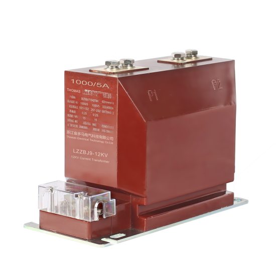
The LZZBJ9-10 current transformer is a resin-insulated, indoor-type instrument transformer designed for accurate current measurement and protection in 10 kV AC power systems operating at 50 Hz or 60 Hz. This device plays a critical role in electrical substations, switchgear assemblies, and industrial power distribution networks by providing scaled-down replicas of high primary currents to connected metering, monitoring, and protective relaying equipment. Its robust epoxy resin encapsulation ensures excellent dielectric strength, mechanical stability, and resistance to environmental contaminants such as moisture, dust, and chemical exposure.
Proper testing and maintenance of the LZZBJ9-10 are essential to guarantee operational reliability, measurement accuracy, and personnel safety. Over time, factors such as thermal cycling, electrical stress, mechanical vibration, and aging of insulation materials can degrade performance or introduce latent faults. Adherence to standardized commissioning procedures and scheduled maintenance routines not only extends the service life of the transformer but also prevents catastrophic failures that could disrupt power supply or damage downstream equipment.
This manual provides comprehensive guidance for qualified electrical engineers and technicians responsible for the installation verification, periodic inspection, and upkeep of LZZBJ9-10 units. It aligns with international standards including IEC 61869-1/-2 (Instrument Transformers), GB/T 20840 (Chinese national standards for instrument transformers), and relevant utility-specific protocols. All procedures assume de-energized conditions unless explicitly stated otherwise, and strict compliance with local electrical safety regulations—including lockout/tagout (LOTO) practices—is mandatory. The information herein applies specifically to the LZZBJ9-10 model rated for 10 kV systems; deviations for other variants should be verified with the manufacturer’s technical documentation.
Commissioning Tests
Commissioning tests are performed immediately after installation and before energizing the LZZBJ9-10 current transformer to verify correct assembly, wiring integrity, insulation condition, and functional accuracy. These tests ensure the unit meets design specifications and is safe for integration into the live power system. All tests must be conducted by certified personnel using calibrated test equipment under controlled environmental conditions (typically 15–35°C ambient temperature and relative humidity below 80%).
The following table outlines the essential commissioning tests, their purpose, acceptable criteria, and required instrumentation:
| Test No. | Test Description | Purpose | Acceptance Criteria | Required Equipment |
|---|---|---|---|---|
| 1 | Visual & Mechanical Inspection | Verify physical integrity, correct labeling, terminal tightness, and absence of shipping damage. | No cracks, deformations, or loose hardware. Nameplate data matches system requirements (e.g., ratio: 100/5 A, accuracy class: 0.5/5P10). | Torque wrench, inspection checklist, magnifying glass |
| 2 | Insulation Resistance Test | Assess dielectric quality of primary-to-secondary and primary-to-ground insulation. | ≥1000 MΩ at 2500 V DC (per IEC 61869). Values significantly lower than factory reports warrant investigation. | Insulation resistance tester (megger) |
| 3 | Winding Polarity Check | Confirm correct dot-marked polarity between primary and secondary windings. | Secondary voltage must rise instantaneously in phase with primary when DC pulse applied. Verified via kick-test or digital polarity checker. | DC source (1.5–12 V battery), analog voltmeter or polarity indicator |
| 4 | Turns Ratio Verification | Validate actual transformation ratio against nameplate rating. | Measured ratio within ±0.5% of nominal (e.g., 100/5 = 20:1 → measured 19.90–20.10:1). | Current transformer turns ratio (TTR) tester |
| 5 | Excitation (Knee-Point) Characteristic Test | Evaluate core saturation behavior and detect shorted turns. | Knee-point voltage ≥ specified value (e.g., ≥500 V for 5P10 class). Curve shape consistent with factory baseline; no abrupt flattening. | Variable AC voltage source, ammeter, voltmeter, or dedicated CT analyzer |
| 6 | Secondary Winding Resistance | Check for open circuits or degraded connections in secondary coil. | Resistance matches factory data ±10% (typically 0.1–0.5 Ω). Balanced across phases in multi-unit installations. | Low-resistance ohmmeter (DLRO) |
| 7 | Burden Verification | Ensure connected load (relays, meters) does not exceed rated burden. | Total burden ≤ transformer’s rated VA (e.g., 15 VA at 0.5 class). Calculated or measured impedance within limits. | Burden tester or multimeter + calculation |
Test Execution Notes:
- All secondary terminals must be short-circuited and grounded during insulation resistance testing of the primary winding.
- For polarity and ratio tests, apply low-voltage excitation to avoid core saturation; never energize the primary from the main bus during commissioning checks.
- Record all test results in the commissioning log, including ambient conditions, equipment serial numbers, and technician identification. Compare against factory test reports provided by the manufacturer.
- If any test fails, isolate the unit and contact the manufacturer before attempting rework or retesting.
Routine Maintenance
Routine maintenance of the LZZBJ9-10 current transformer is crucial for sustaining long-term performance, ensuring measurement fidelity, and preventing unexpected outages. Unlike oil-filled transformers, the resin-insulated LZZBJ9-10 requires minimal intervention but remains susceptible to surface contamination, terminal corrosion, and mechanical loosening over time. A structured maintenance program—typically conducted annually or biennially depending on operating environment severity—helps identify incipient faults before they escalate.
Maintenance activities should be scheduled during planned outages, with the associated circuit fully de-energized and grounded. Personnel must wear appropriate PPE and follow site-specific safety protocols. The following table details recommended routine maintenance tasks, their frequency, and key inspection points:
| Maintenance Task | Frequency | Key Inspection/Action Points | Acceptable Condition |
|---|---|---|---|
| Visual Inspection | Annual | Examine housing for cracks, tracking marks, discoloration, or resin degradation. Check for dust, salt, or conductive deposits on surface. | Housing intact, clean, and free of carbonized paths or moisture ingress signs. |
| Terminal Tightness Check | Biennial | Inspect primary busbar connections and secondary screw terminals for looseness, oxidation, or overheating (discoloration). | Torque values per manufacturer spec (e.g., 15–20 N·m for M8 bolts). No pitting or green corrosion on copper contacts. |
| Cleanliness Maintenance | As needed / Annual | Clean external surfaces with dry lint-free cloth. For heavy contamination, use mild detergent and distilled water; avoid solvents. | Dry, non-conductive surface with no residue. Ensure complete drying before re-energization. |
| Insulation Resistance Re-test | Every 3–5 years | Repeat megger test under same conditions as commissioning. Compare trend with historical data. | No significant decline (>20%) from baseline. Absolute value still ≥500 MΩ. |
| Secondary Circuit Integrity | Annual | Verify continuity of secondary wiring, check for broken strands, and confirm grounding at one point only. | No open circuits; grounding secure and single-point to prevent circulating currents. |
| Accuracy Spot-Check | Every 5 years or after fault events | Perform simplified ratio and polarity test using portable TTR kit. | Ratio error within ±1.0%; polarity confirmed correct. |
Maintenance Best Practices:
- Always document findings in a maintenance logbook, noting deviations, corrective actions, and component replacements.
- In coastal or industrial environments with high pollution, increase inspection frequency to semi-annual.
- Never attempt internal repairs—the LZZBJ9-10 is a sealed, non-serviceable unit. Replace if internal faults are suspected.
- After any maintenance involving secondary wiring, re-verify burden and perform a functional test with connected protection relays.
4. Periodic Testing
Periodic testing is a scheduled, systematic evaluation of electrical, mechanical, and safety systems to ensure continued compliance with operational standards and regulatory requirements. Conducted at predetermined intervals—such as monthly, quarterly, semi-annually, or annually—these tests help identify degradation, wear, or latent faults before they lead to system failure. The scope of periodic testing varies by asset type, criticality, and environmental exposure. For example, emergency lighting systems may require monthly functional checks and annual duration tests, while medium-voltage switchgear might undergo dielectric and thermal imaging inspections every three years.
Key objectives include verifying performance against design specifications, validating protective device coordination, and confirming that safety interlocks operate correctly. Testing protocols must align with recognized standards such as NFPA 70B (Recommended Practice for Electrical Equipment Maintenance), IEEE 43 (Insulation Resistance Testing), and ISO 55000 (Asset Management). Personnel performing these tests must be qualified and use calibrated instruments to ensure data accuracy and repeatability.
The following table outlines common periodic testing activities by system category:
| System Category | Test Type | Typical Frequency | Key Parameters Measured |
|---|---|---|---|
| Electrical Distribution | Insulation Resistance Test | Annually | Megohm values, polarization index |
| Emergency Power | Load Bank Test | Annually | Voltage stability, frequency response, exhaust temperature |
| Fire Alarm Systems | Functional Verification | Quarterly | Detector activation, control panel response, notification appliance operation |
| Motor Control Centers | Thermal Imaging | Semi-annually | Hot spots, connection integrity, load imbalance |
| Grounding Systems | Fall-of-Potential Test | Every 3 Years | Earth resistance (ohms) |
Documentation of test results, including pass/fail status, deviations, and corrective actions, is essential for audit readiness and trend analysis. Any out-of-tolerance result must trigger a formal review and, if necessary, immediate remediation to prevent operational risk.
5. Diagnostic Testing
Diagnostic testing is performed to investigate specific anomalies, performance issues, or suspected failures in equipment or systems. Unlike periodic testing, which follows a fixed schedule, diagnostic testing is reactive or condition-triggered, often initiated after an alarm, unexpected shutdown, or abnormal reading from monitoring systems. Its primary goal is to isolate the root cause of a problem with minimal disruption to operations.
This form of testing employs advanced tools and techniques such as power quality analyzers, vibration sensors, oil sampling (for transformers), partial discharge detectors, and thermographic cameras. For instance, if a motor exhibits excessive vibration, a diagnostic team may conduct spectral analysis to determine whether the issue stems from misalignment, bearing wear, or electrical imbalance. Similarly, dissolved gas analysis (DGA) in transformer oil can reveal incipient faults like arcing or overheating long before catastrophic failure occurs.
Diagnostic testing requires skilled technicians who can interpret complex data and correlate findings across multiple measurement domains. Results are typically used to support repair decisions, estimate remaining useful life, or justify equipment replacement. Because of its targeted nature, diagnostic testing is highly efficient in resource utilization but demands precise problem definition to be effective.
| Symptom | Diagnostic Method | Possible Root Causes Identified |
|---|---|---|
| Overheating Busbar | Infrared Thermography + Torque Verification | Loose connection, corrosion, overload |
| Unstable Voltage | Power Quality Analyzer | Harmonic distortion, utility-side fluctuation, capacitor bank failure |
| Unexpected Relay Trip | Relay Settings Audit + Secondary Injection Test | Incorrect settings, CT saturation, wiring fault |
| Noisy Transformer | Acoustic Monitoring + DGA | Core looseness, internal arcing, winding deformation |
6. Troubleshooting
Troubleshooting is a structured methodology used to identify, analyze, and resolve operational faults in industrial or facility systems. It begins when a deviation from normal operation is observed—such as a machine shutdown, loss of communication, or safety system activation—and continues until full functionality is restored. Effective troubleshooting relies on logical sequencing, technical knowledge, access to schematics, and adherence to safety protocols like lockout/tagout (LOTO).
The process typically follows a step-by-step approach: (1) define the problem clearly, (2) gather relevant data (error codes, operator observations, historical logs), (3) develop hypotheses based on system knowledge, (4) test each hypothesis systematically, and (5) implement and verify the solution. Skilled troubleshooters avoid assumptions and instead use evidence-based reasoning to narrow down potential causes. For example, if a conveyor belt fails to start, the technician might first verify power supply, then check motor starter contacts, followed by inspecting limit switches and PLC outputs.
Modern troubleshooting often integrates digital tools such as PLC diagnostics software, network analyzers, and mobile maintenance apps that provide real-time access to equipment manuals and past work orders. Cross-functional collaboration—between electricians, mechanics, and control engineers—is frequently necessary for complex systems. Importantly, troubleshooting should not end with a quick fix; underlying systemic issues (e.g., recurring sensor failures due to poor environmental protection) must be addressed to prevent recurrence.
The following table illustrates a generalized troubleshooting workflow for common electrical faults:
| Fault Symptom | Initial Checks | Advanced Diagnostics | Common Resolutions |
|---|---|---|---|
| Circuit Breaker Tripping | Load measurement, visual inspection for damage | Insulation resistance test, thermal scan | Reduce load, replace faulty breaker, repair short circuit |
| PLC I/O Not Responding | Verify power to I/O module, check wiring | Loop calibration, signal simulation | Re-seat module, replace blown fuse, correct wiring error |
| Motor Overheating | Ambient temperature, cooling fan operation | Vibration analysis, current imbalance test | Clean ventilation, realign coupling, balance phases |
| Ground Fault Alarm | Isolate circuits, check GFCI/RCD operation | Megger test on branch circuits | Replace damaged cable, dry out conduit, reset/replace GFCI |
Post-resolution documentation is critical—not only to close the work order but also to contribute to a knowledge base that accelerates future troubleshooting efforts.
7. Record Keeping
Accurate and comprehensive record keeping is fundamental to effective maintenance management, regulatory compliance, and continuous improvement. All testing, diagnostic, and troubleshooting activities must be documented in a structured format that captures key details: date, personnel involved, equipment ID, procedures followed, instruments used, raw data, observed conditions, conclusions, and actions taken. These records serve multiple purposes—supporting warranty claims, enabling trend analysis, facilitating audits, and providing legal defensibility in case of incidents.
Records should be maintained in a centralized system, preferably a Computerized Maintenance Management System (CMMS), which ensures version control, accessibility, and integration with work order histories. Paper logs are acceptable only if digitization is impractical, but they must be stored securely and indexed for retrieval. Regulatory bodies such as OSHA, EPA, and local fire marshals often require retention periods of 3–7 years for certain records (e.g., arc flash studies, confined space entries, or pressure vessel inspections).
| Record Type | Retention Period | Required Elements |
|---|---|---|
| Periodic Test Reports | 5 Years | Test standard, instrument calibration ID, pass/fail criteria, technician signature |
| Troubleshooting Logs | 3 Years | Problem description, steps taken, parts replaced, verification method |
| Calibration Certificates | 7 Years | Pre- and post-calibration data, tolerance limits, accredited lab info |
| Maintenance Work Orders | Life of Asset + 2 Years | Asset tag, labor hours, materials used, completion notes |
Digital records should be backed up regularly and protected against unauthorized modification to preserve integrity.
8. Maintenance Planning
Maintenance planning ensures that all testing, diagnostic, and corrective activities are executed efficiently, safely, and with minimal impact on operations. It involves coordinating resources—including personnel, tools, spare parts, and downtime windows—in advance of work execution. A well-developed plan reduces reactive work, controls costs, and enhances reliability by aligning maintenance tasks with production schedules and asset criticality rankings.
Effective planning begins with a detailed work scope derived from inspection findings, CMMS alerts, or predictive analytics. Planners then identify required skills, estimate duration, secure permits (e.g., hot work, confined space), and stage materials. For major overhauls, a job plan may include risk assessments, method statements, and contingency measures. Integration with inventory systems prevents delays due to part unavailability, while coordination with operations ensures that maintenance windows do not conflict with peak production.
| Planning Element | Description |
|---|---|
| Task Definition | Clear description of work to be performed, including safety precautions |
| Resource Allocation | Assignment of qualified technicians and specialized equipment |
| Parts & Materials | Verification of availability and kitting prior to job start |
| Scheduling | Alignment with operational downtime and crew availability |
Continuous feedback from completed work orders refines future planning accuracy, creating a cycle of improvement that boosts overall maintenance effectiveness.