Article Content
11kV Cast-Resin Voltage Transformer JDZW-10R for Metering and Protection – IEC 61869-3 Standard
Introduction to the JDZW-10R Voltage Transformer
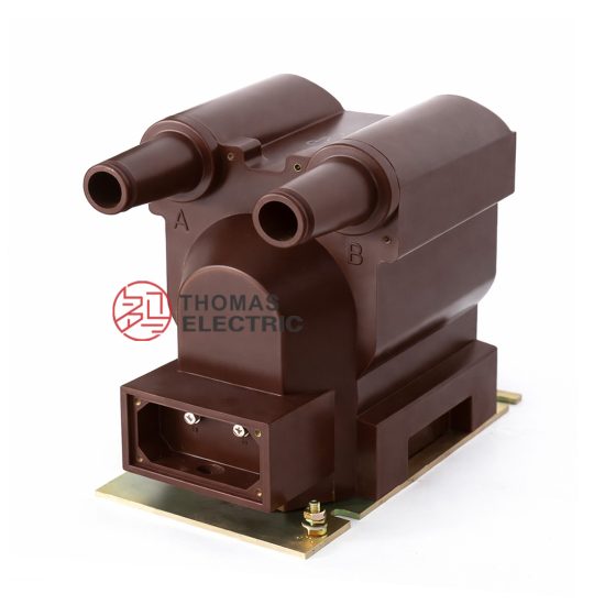
The JDZW-10R is a single-phase, indoor/outdoor-rated cast-resin insulated voltage transformer (VT) designed for accurate voltage measurement and reliable protective relay operation in medium-voltage power systems rated at 11kV (IEC standard) or 10kV (domestic Chinese system). As a critical component in secondary instrumentation circuits, it provides galvanic isolation between high-voltage primary conductors and low-voltage metering, monitoring, and protection devices. The transformer operates on the principle of electromagnetic induction, where the primary winding—connected phase-to-ground—induces a proportional secondary voltage across one or more secondary windings, typically standardized at 100 V or 100/√3 V.
Cast-Resin Insulation Technology
The JDZW-10R employs vacuum pressure impregnation (VPI) epoxy resin casting technology to encapsulate its magnetic core and windings. This process eliminates air voids and moisture ingress by fully saturating the insulation system under controlled vacuum and pressure conditions. The resulting monolithic structure offers superior dielectric strength, tracking resistance, and mechanical rigidity compared to traditional oil-filled or dry-wound designs. Epoxy resin’s high thermal conductivity (≈0.2 W/m·K) enables efficient heat dissipation, supporting continuous operation under load without thermal degradation. Additionally, the absence of flammable oil enhances fire safety—making the JDZW-10R suitable for urban substations, industrial facilities, and confined indoor switchgear where environmental and safety regulations are stringent.
Advantages Over Oil-Immersed Designs
Unlike oil-immersed VTs, the JDZW-10R requires no oil containment, periodic oil sampling, or risk of leakage—significantly reducing lifecycle maintenance costs. Its solid insulation system is immune to oil oxidation, sludge formation, and dielectric breakdown due to moisture contamination. The compact footprint (typically 30–40% smaller than equivalent oil units) facilitates easier integration into ring main units (RMUs) and compact secondary substations. Furthermore, cast-resin VTs exhibit excellent partial discharge performance (<10 pC at 1.2 × Ur), ensuring long-term reliability even under transient overvoltages. Environmental compliance is also enhanced, as the unit contains no hazardous substances regulated under RoHS or REACH directives.
Typical Application Context
The JDZW-10R is engineered for deployment in 10kV/11kV distribution networks where precision, safety, and minimal maintenance are paramount. Common installations include utility-owned primary substations, commercial building switchrooms, solar inverter stations, and railway traction feeders. Its dual secondary windings (e.g., 0.5/3P accuracy classes) allow simultaneous connection to revenue metering and overvoltage/undervoltage protection relays. The transformer’s robust design withstands switching surges and lightning impulses per IEC 60060, making it ideal for regions with high lightning density or frequent capacitor bank switching.
Technical Specifications
The JDZW-10R adheres to precise electrical and mechanical parameters defined by IEC 61869-3 and GB/T 20840.3. Below is a representative specification table based on standard configurations:
| Parameter | Value |
|---|---|
| System Voltage (Ur) | 11 kV (IEC) / 10 kV (GB) |
| Primary Voltage | 11/√3 kV (phase-to-ground) |
| Secondary Voltages | 100/√3 V (metering), 100/√3 V (protection) |
| Voltage Ratio | (11000/√3) : (100/√3) : (100/√3) |
| Accuracy Class | 0.5 (metering), 3P (protection) |
| Rated Output (per winding) | 30 VA (0.5 class), 50 VA (3P class) |
| Burden Limit | Max total burden ≤ 80 VA |
| Insulation Level (LI/AC) | 75 kV (lightning impulse), 42 kV (power frequency, 1 min) |
| Partial Discharge | <10 pC at 1.2 × Ur |
| Core Material | Grain-Oriented Electrical Steel (GOES), M4 grade |
| Frequency | 50 Hz (±0.5 Hz) |
| Ambient Temperature | –25°C to +40°C |
| Altitude | ≤1000 m above sea level |
| Relative Humidity | ≤95% (non-condensing) |
Electrical Performance Characteristics
The JDZW-10R delivers high metrological fidelity under varying load conditions. At rated burden (30 VA for 0.5 class), voltage error remains within ±0.5%, and phase displacement is ≤20 minutes. For protection-class windings (3P), composite error stays below 3% at 5× rated voltage during fault conditions. The transformer exhibits low temperature rise (<55 K above ambient) under continuous full-load operation, verified per IEC 61869-3 thermal tests. Its magnetizing current is typically <0.5% of rated primary current, minimizing excitation losses and ensuring stable performance during light-load scenarios common in rural distribution networks.
Environmental and Mechanical Ratings
Designed for both indoor and outdoor use, the JDZW-10R features UV-stabilized epoxy housing with IP54 ingress protection when installed with sealed terminal boxes. The creepage distance exceeds 25 mm/kV (medium pollution environment per IEC 60815), preventing flashovers in coastal or industrial atmospheres. Mounting is via M12 stainless steel bolts on a standardized base plate (200×200 mm pattern). Terminal markings comply with IEC 61869-3 polarity conventions: A–a (reducing polarity), with secondary terminals labeled da–dn for residual voltage windings if present. The unit weighs approximately 45 kg, facilitating manual handling during installation.
Typical Applications
Substation Secondary Metering Systems
In utility-owned 11kV/0.4kV distribution substations, the JDZW-10R supplies accurate voltage signals to kWh meters, power quality analyzers, and SCADA RTUs. Its 0.5-class winding ensures billing-grade accuracy even under harmonic distortion (THD ≤5%). For example, in a Shanghai municipal substation, JDZW-10R units feed data to AMI (Advanced Metering Infrastructure) systems, enabling real-time loss calculation and demand forecasting. The cast-resin design eliminates oil-related maintenance, critical in unmanned substations monitored remotely.
Industrial Power Distribution Monitoring
Large manufacturing plants—such as automotive assembly lines or semiconductor fabs—use the JDZW-10R to monitor voltage stability across 10kV busbars. Sudden sags or swells can disrupt sensitive equipment; thus, the VT’s fast response (<20 ms) to transients allows protective relays (e.g., SEL-751) to initiate corrective actions. In a Guangdong electronics plant, JDZW-10R transformers enabled detection of recurring 8% undervoltage events linked to upstream capacitor switching, leading to system reconfiguration.
Renewable Energy Integration
Solar PV and wind farms operating at 10kV/11kV grid connection points rely on the JDZW-10R for synchronization and anti-islanding protection. During grid faults, the protection-class (3P) winding provides reliable voltage collapse detection to trigger disconnection per IEEE 1547. In a 20 MW solar farm in Inner Mongolia, JDZW-10R units interface with digital relays to enforce ride-through requirements while maintaining metering accuracy for feed-in tariff calculations.
Rural and Suburban Distribution Networks
In remote areas with limited maintenance access, the JDZW-10R’s maintenance-free design ensures decades of service. Its tolerance to wide temperature swings (–25°C to +40°C) suits northern Chinese winters and southern summers. A case study in Yunnan province showed zero failures over 8 years in 12 villages, where units supply voltage data to pole-mounted smart meters and fault indicators.
Testing and Calibration Laboratories
Calibration labs use the JDZW-10R as a reference standard for verifying other VTs or energy meters. Its low phase error (<10 minutes at 0.5 class) and stable ratio under varying burdens make it ideal for traceable measurements per ISO/IEC 17025. Labs often perform annual ratio verification using precision bridges (e.g., Omicron CT Analyzer), leveraging the JDZW-10R’s documented repeatability.
Compliance with International Standards
IEC 61869-3 Certification Requirements
The JDZW-10R is fully compliant with IEC 61869-3:2011 (“Instrument transformers – Part 3: Particular requirements for inductive voltage transformers”). This standard mandates rigorous type tests including temperature rise, short-circuit withstand (for VTs, simulated via open-circuit test), insulation coordination, and accuracy verification across burden ranges. Certification involves third-party witnessing by accredited bodies (e.g., KEMA, CESI), with test reports documenting performance at 80%, 100%, and 120% of rated voltage. Key clauses addressed include Clause 6.3 (rated insulation levels) and Clause 7.2 (accuracy limits under specified burdens).
Alignment with GB/T 20840.3
In China, the JDZW-10R meets GB/T 20840.3-2013, which harmonizes with IEC 61869-3 but includes localized requirements. Notably, GB/T specifies a slightly lower power frequency withstand voltage (42 kV vs. IEC’s 46 kV for 12 kV systems) and mandates additional seismic testing (0.3g horizontal acceleration) for earthquake-prone regions. The domestic standard also defines 10kV as the nominal system voltage, whereas IEC uses 11kV—requiring dual labeling on nameplates. Despite these nuances, the core design principles remain consistent, enabling global interoperability.
Key Differences Between IEC and GB Standards
While IEC 61869-3 emphasizes international harmonization, GB/T 20840.3 incorporates China-specific grid characteristics. For instance, GB requires verification of accuracy at 20% of rated voltage (simulating light-load rural conditions), whereas IEC focuses on 80–120% range. Additionally, GB mandates higher creepage distances (≥31 mm/kV for heavy pollution zones) compared to IEC’s baseline 25 mm/kV. Manufacturers like DuomaTech produce JDZW-10R variants with extended sheds to meet both standards simultaneously, ensuring export readiness and domestic compliance.
On-Site Testing Procedures
Insulation Resistance Test
Conducted using a 2500 V DC megohmmeter per IEC 60270. Primary-to-ground and secondary-to-ground insulation must exceed 1000 MΩ at 20°C. Measurements are corrected to 20°C using the formula R20 = Rt × 2(t–20)/10. Values below 500 MΩ indicate moisture ingress or resin cracking and warrant further investigation via tan delta testing. This test is performed before energization and annually thereafter.
Turns Ratio Verification
Using a ratio bridge (e.g., Omicron CPC 100), apply 100–200 V to the primary and measure secondary output. The measured ratio must match the nameplate within ±0.2% for 0.5-class windings. For a (11000/√3):(100/√3) ratio, expected secondary is 100 V ±0.2 V at 11 kV primary equivalent. Deviations >0.5% suggest turn-to-turn shorts or winding damage.
Polarity Confirmation
Verify reducing polarity per IEC 61869-3 Annex B. Apply a 6–12 V DC pulse to primary (A positive, X negative); a momentary positive deflection on a DC voltmeter connected to secondary (a positive, x negative) confirms correct polarity. Incorrect polarity causes 180° phase reversal, leading to metering errors or relay misoperation.
Power Frequency Withstand Voltage Test
Apply 42 kV AC (RMS) at 50 Hz between primary and grounded tank/secondary for 1 minute. No flashover or disruptive discharge is permitted. This test validates insulation integrity after transport or prolonged storage. It is typically performed only during commissioning or post-fault assessment—not routinely.
Open-Circuit Characteristic Test
Gradually increase primary voltage from 20% to 120% of Ur while measuring secondary voltage and excitation current. Plot Vs vs. Iexc. A sharp current rise above 100% Ur indicates core saturation; the knee point should occur ≥120% Ur. This test detects core lamination damage or shorted turns invisible to ratio tests.
Preventive Maintenance Guide
Annual Visual and Functional Inspection
Inspect for surface cracks, tracking marks, or discoloration on the resin housing. Check terminal tightness (torque: 15 N·m for M8 bolts) and corrosion on grounding lugs. Verify secondary wiring integrity and burden connections. Perform insulation resistance and ratio tests as baseline metrics. Document all readings for trend analysis—sudden drops in insulation resistance often precede failure.
Five-Year Comprehensive Maintenance
At five-year intervals, conduct partial discharge (PD) measurement using IEC 60270 methods. Acceptable PD magnitude is <10 pC at 1.2 × Ur. Also, clean the housing with non-abrasive detergent to remove conductive dust layers that could reduce surface resistivity. Re-torque all mechanical fasteners and inspect mounting hardware for fatigue. If installed outdoors, verify gasket integrity on terminal boxes to maintain IP54 rating.
Fault Diagnosis and Troubleshooting
Common failure modes include open secondary circuits (causing dangerous overvoltages), moisture-induced insulation degradation, and core saturation due to ferroresonance. Symptoms include blown fuses on secondary side, erratic meter readings, or audible humming. Diagnose by comparing phase voltages—if one VT shows 150 V while others read 100 V, suspect ferroresonance from ungrounded systems. Mitigation includes installing damping resistors across open-delta secondaries.
| Maintenance Interval | Activities |
|---|---|
| Initial Commissioning | Full suite: IR, ratio, polarity, withstand, open-circuit |
| Annually | Visual inspection, IR test, ratio check |
| Every 5 Years | PD test, cleaning, torque verification, gasket inspection |
| Post-Fault | Withstand test, open-circuit curve, core inspection if accessible |
Conclusion
The JDZW-10R 11kV cast-resin voltage transformer represents a benchmark in reliability, accuracy, and compliance for modern medium-voltage infrastructure. By leveraging advanced VPI epoxy resin technology and GOES silicon steel cores, it delivers exceptional dielectric performance, thermal stability, and immunity to environmental stressors—outperforming legacy oil-immersed alternatives in both operational safety and lifecycle cost. Its dual-winding configuration (0.5/3P) satisfies concurrent metering and protection demands without compromise, while strict adherence to IEC 61869-3 and GB/T 20840.3 ensures global acceptance and regulatory alignment. Field-proven across diverse applications—from dense urban substations to remote renewable sites—the JDZW-10R demonstrates minimal drift in ratio and phase error over time, supported by a design life of 25–30 years under standard service conditions. When paired with disciplined preventive maintenance (annual IR/ratio tests and quinquennial PD assessments), this VT provides decades of trouble-free service, making it a strategic asset for utilities and industrial operators prioritizing grid resilience and measurement integrity.
Frequently Asked Questions (FAQ)
Q1: Can the JDZW-10R be used in a 10kV system even though it’s rated 11kV?
A: Yes. The 11kV rating aligns with IEC’s highest voltage for equipment (Um = 12 kV), making it suitable for 10kV nominal systems (Un = 10 kV) per GB standards. The insulation level (42 kV AC withstand) exceeds requirements for 10kV networks.
Q2: What is the maximum allowable burden for the JDZW-10R?
A: Total connected burden must not exceed 80 VA. Exceeding this causes increased ratio error and phase displacement beyond accuracy class limits. Always sum VA ratings of all connected devices (meters, relays, leads).
Q3: Is the JDZW-10R suitable for outdoor installation?
A: Yes, provided the terminal box is sealed to IP54. The epoxy housing is UV-resistant and rated for –25°C to +40°C ambient. In heavy pollution zones, specify extended creepage variants.
Q4: How often should partial discharge testing be performed?
A: PD testing is recommended every 5 years or after severe overvoltage events. Baseline PD <10 pC at 1.2 × Ur indicates healthy insulation.
Q5: What causes ferroresonance in JDZW-10R installations?
A: Ferroresonance occurs when a VT is connected to an ungrounded or high-impedance grounded system with significant cable capacitance. Mitigate by installing 100–500 Ω damping resistors across the open-delta secondary.
Q6: Can the secondary windings be paralleled?
A: No. Paralleling windings of different accuracy classes (e.g., 0.5 and 3P) distorts burden distribution and compromises accuracy. Each winding must feed independent circuits.