Article Content
Introduction to the UTF-8 Current Transformer
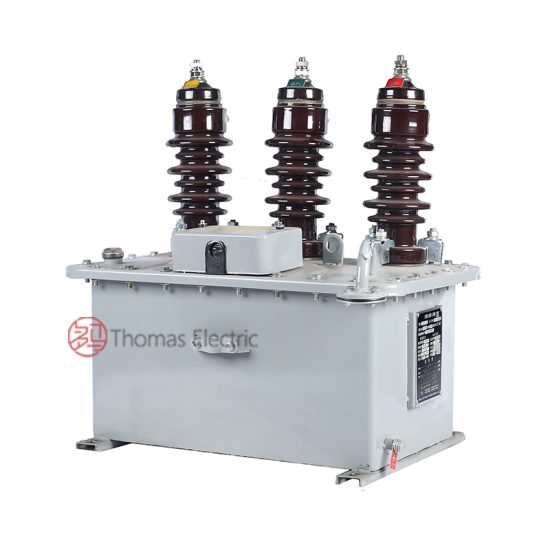
The UTF-8 is a high-reliability, 11kV (IEC-rated) / 10kV (domestic system equivalent) cast-resin current transformer engineered for precision metering and robust protection in medium-voltage substations and industrial power networks. Designed in strict accordance with IEC 61869-2 and GB/T 20840.2, this instrument transformer leverages advanced vacuum pressure impregnation (VPI) epoxy resin technology to encapsulate its magnetic core and windings, ensuring long-term dielectric integrity and environmental resilience.
Operating Principle of Cast-Resin Insulation
Cast-resin insulation in the UTF-8 CT employs a two-component cycloaliphatic epoxy resin system cured under controlled vacuum and pressure conditions. This VPI process eliminates air voids and moisture ingress pathways, resulting in a homogeneous, non-hygroscopic solid dielectric with a relative permittivity (εr) of approximately 3.8–4.2 and volume resistivity exceeding 1×10¹⁴ Ω·cm at 20°C. The resin matrix provides mechanical support to the primary conductor and secondary windings while maintaining stable partial discharge inception voltage (PDIV) above 25 kV (peak) under standard test conditions. Unlike oil-filled alternatives, the solid insulation eliminates fire hazards, leakage risks, and maintenance associated with fluid containment, making it ideal for indoor switchgear, urban substations, and environmentally sensitive installations.
Advantages Over Oil-Immersed Designs
Compared to traditional oil-immersed CTs, the UTF-8’s cast-resin construction offers superior operational safety, reduced lifecycle costs, and enhanced environmental compatibility. The absence of flammable insulating oil eliminates explosion and fire propagation risks—critical in confined or public-access areas. Additionally, the solid resin exhibits negligible aging under thermal cycling between –40°C and +40°C ambient temperatures, with no degradation in dielectric strength over decades of service. Mechanical robustness is further improved through integral flange mounting and reinforced bushing design, resisting vibration from nearby circuit breakers or transformers. Maintenance intervals are extended significantly, as there is no need for oil sampling, gas analysis, or tank sealing inspections. These attributes make the UTF-8 particularly suited for smart grid infrastructure where reliability and minimal intervention are paramount.
Typical Applications Overview
The UTF-8 is deployed across a spectrum of medium-voltage applications requiring accurate current transformation with high short-circuit withstand capability. Primary use cases include revenue metering in utility distribution substations, overcurrent and differential protection in industrial motor control centers, and harmonic monitoring in renewable energy interconnection points (e.g., solar farms operating at 10kV/11kV). Its compact footprint and IP54-rated terminal box facilitate integration into ring main units (RMUs), metal-clad switchgear, and pad-mounted transformers. With a standard short-time thermal current rating of 20 kA for 1 second and dynamic withstand up to 50 kA peak, the UTF-8 reliably operates under fault conditions without core saturation or insulation failure, ensuring continuity of protective relay operation.
Technical Specifications
The UTF-8 current transformer is engineered to meet stringent performance criteria under both international (IEC) and domestic (GB) standards. Below is a detailed specification table followed by environmental and operational parameters.
| Parameter | Value |
|---|---|
| Rated Voltage (Um) | 11 kV (IEC) / 10 kV (GB) |
| Primary Current (Ip) | 50 A to 3000 A (standard); custom ratios available |
| Secondary Current (Is) | 1 A or 5 A |
| Accuracy Class (Metering) | 0.2, 0.5, 1.0 per IEC 61869-2 |
| Accuracy Class (Protection) | 5P10, 5P20, 10P10, 10P20 |
| Rated Output (Burden) | 2.5 VA to 30 VA (at rated accuracy) |
| Insulation Level (LI/AC) | 75 kV / 28 kV (1 min, 50 Hz) |
| Short-Time Thermal Current | 20 kA for 1 s (up to 31.5 kA optional) |
| Dynamic Withstand Current | 50 kA peak |
| Core Material | Grain-Oriented Electrical Steel (GOES), M4 grade |
| Insulation System | VPI cycloaliphatic epoxy resin, UL 94 V-0 rated |
| Terminal Box Rating | IP54, brass terminals with anti-rotation screws |
Standard Service Conditions
The UTF-8 is rated for continuous operation under the following standard environmental conditions as defined in IEC 61869-2 Clause 5: ambient temperature range of –40°C to +40°C, relative humidity up to 100% (condensing permitted), and installation altitude not exceeding 1000 meters above sea level. For altitudes between 1000 m and 3000 m, derating factors apply to the power frequency withstand voltage (reduced by 1% per 100 m above 1000 m). The transformer is suitable for both indoor and outdoor installation, with UV-stabilized resin formulation preventing surface cracking or chalking under prolonged solar exposure. Pollution degree is classified as III per IEC 60664-1, supporting use in industrial atmospheres with conductive dust or chemical vapors.
Core and Winding Design
The magnetic circuit utilizes high-permeability grain-oriented electrical steel (GOES) laminations, annealed to minimize hysteresis losses and ensure low excitation current (< 0.5% of rated secondary current at 100% burden). Secondary windings are wound with oxygen-free copper (OFC) wire, insulated with Class F (155°C) enamel, and embedded directly into the resin matrix during casting to prevent movement under electromagnetic forces. Multiple secondary windings can be provided (e.g., one for metering, one for protection) with galvanic isolation between cores. The primary conductor is a solid copper bar or tubular busbar, sized to handle continuous current without exceeding 65 K temperature rise above ambient. All internal connections are ultrasonically welded to eliminate contact resistance variability.
Typical Applications
The UTF-8 cast-resin current transformer serves critical roles across diverse power infrastructure segments, combining metrological accuracy with rugged protection performance.
Substation Secondary Metering
In 11kV/10kV distribution substations, the UTF-8 provides Class 0.2 or 0.5 current signals to revenue-grade energy meters and SCADA systems. Its low phase displacement error (< ±10 minutes at 100% load) ensures compliance with billing accuracy requirements under varying load profiles. Installation typically occurs on outgoing feeders or incomer circuits, where the CT’s compact dimensions allow retrofitting into existing switchgear without busbar modifications. The sealed terminal box prevents tampering and moisture ingress, critical for maintaining audit trails in regulated utility environments.
Industrial Power Distribution
Within manufacturing plants and data centers, the UTF-8 supports motor protection relays (e.g., 50/51 functions) and power quality analyzers. Its 5P20 or 10P20 protection class guarantees linear response up to 20 times rated current, enabling precise fault discrimination during motor start-up inrush or downstream short circuits. The transformer’s high dynamic withstand (50 kA peak) ensures mechanical integrity during bolted faults, preventing core deformation that could compromise future relay coordination. Integration with digital relays via 1 A secondary outputs reduces copper losses in long cable runs to control rooms.
Renewable Energy Integration
Solar photovoltaic and wind farms operating at 10kV/11kV utilize the UTF-8 for grid interconnection monitoring and anti-islanding protection. The CT’s wide frequency response (45–65 Hz) accommodates inverter-induced harmonics without significant ratio error increase. In microgrid applications, dual-core UTF-8 units supply separate signals to revenue meters and synchrophasor measurement units (PMUs), enabling real-time stability assessment. The cast-resin body resists salt fog and sand abrasion in coastal or desert installations, outperforming oil-filled alternatives prone to gasket degradation.
Rural and Suburban Distribution Networks
For overhead line pole-mounted transformers and underground residential feeders, the UTF-8’s lightweight design (typically 12–18 kg) simplifies field handling and reduces structural loading on poles or vaults. Its immunity to freezing eliminates winter operational failures common in oil-filled units. Utilities deploy UTF-8 CTs in automated feeder sectionalizers, where consistent ratio accuracy across temperature extremes ensures reliable recloser coordination during tree-contact faults or animal intrusions.
Harmonic-Rich Environments
In facilities with variable frequency drives (VFDs) or arc furnaces, the UTF-8’s low remanence core minimizes residual flux buildup during asymmetric fault clearing, reducing risk of protection blinding. Testing per IEC 61869-2 Annex D confirms ratio error remains within ±0.5% even with 15% third-harmonic content, supporting accurate harmonic distortion measurements for IEEE 519 compliance verification.
Compliance with International Standards
The UTF-8 current transformer is certified to IEC 61869-2:2012 (“Instrument transformers – Part 2: Additional requirements for current transformers”) and fully aligned with China’s GB/T 20840.2-2014 standard, which adopts IEC 61869-2 with minor national deviations.
IEC 61869-2 Compliance Details
Compliance encompasses all mandatory tests in IEC 61869-2 Clauses 7–10, including temperature rise (≤ 60 K for windings), short-circuit withstand (thermal and dynamic), and accuracy verification under specified burdens. The standard mandates that ratio error and phase displacement be measured at 5%, 20%, 100%, and 120% of rated current for metering classes, and at 100% and rated accuracy limit factor (e.g., 20×In) for protection classes. The UTF-8 undergoes type testing at accredited laboratories, with results documented in test reports traceable to national metrology institutes. Partial discharge levels are verified to be ≤ 10 pC at 1.2 × Um/√3, well below the 50 pC limit in Clause 8.4.
GB/T 20840.2 Alignment and National Deviations
While GB/T 20840.2 mirrors IEC 61869-2 structurally, key differences include: (1) requirement for lightning impulse test at 95 kV (vs. IEC’s 75 kV for 11kV class), reflecting China’s higher insulation coordination practices; (2) mandatory seismic qualification per GB/T 13540 for regions with seismic intensity ≥ VII; and (3) stricter marking requirements including Chinese language labels and QR-code traceability. The UTF-8 meets all GB-specific tests, with impulse withstand validated at 95 kV (1.2/50 μs wave) and seismic performance confirmed for 0.3g horizontal acceleration. These adaptations ensure seamless acceptance by State Grid Corporation and China Southern Power Grid procurement specifications.
Certification and Quality Assurance
Each UTF-8 unit carries CE marking per EU Low Voltage Directive 2014/35/EU and bears a unique serial number linked to factory test records. Routine production tests include power frequency withstand (28 kV, 1 min), insulation resistance (> 1000 MΩ at 2500 V DC), and polarity verification. Type tests are repeated every five years or after design changes. Third-party certification from bodies such as TÜV Rheinland or CQC validates ongoing compliance.
On-Site Testing Procedures
Post-installation and periodic field testing ensures the UTF-8 maintains performance integrity throughout its service life. All procedures follow IEC 61869-2 Annex B and IEEE C57.13.6 guidelines.
Insulation Resistance Test
Using a 2500 V DC megohmmeter, measure insulation resistance between primary-to-secondary, primary-to-ground, and secondary-to-ground. Acceptance criterion: ≥ 1000 MΩ at 20°C. Correct for temperature using RT = R20 × 2(20–T)/10. Values below 500 MΩ indicate moisture ingress or resin cracking and warrant further investigation via tan delta or partial discharge testing. Perform before and after power frequency withstand tests to detect insulation degradation.
Turns Ratio Test
Apply a low-voltage AC source (5–10 V) to the secondary winding and measure induced primary voltage, or use a dedicated ratio bridge. Verify ratio error against nameplate values. Tolerance: ±0.25% for Class 0.2, ±0.5% for Class 0.5, and ±1.0% for protection classes at 100% rated current. For multi-ratio CTs, test all tap combinations. Significant deviation (>2%) suggests turn-to-turn shorts or incorrect tapping.
Polarity Test
Confirm reducing polarity (IEC standard) using the DC kick method: momentarily connect a 6–12 V battery across P1–P2; observe secondary voltage deflection on a center-zero galvanometer connected to S1–S2. A positive kick at S1 when P1 is energated confirms correct polarity. Incorrect polarity causes 180° phase reversal, leading to relay misoperation or metering errors. Document results with oscillograms if digital relays are involved.
Power Frequency Withstand Voltage Test
Apply 28 kV RMS (50 Hz) for 1 minute between primary and grounded secondary/enclosure. Use a calibrated test transformer with overcurrent trip set at 10 mA. No flashover or disruptive discharge constitutes pass. Reduce voltage gradually post-test to avoid transient overvoltages. This test validates dielectric integrity after transportation or installation stress.
Excitation (Saturation) Characteristic Test
For protection-class CTs, perform open-circuit secondary excitation: incrementally apply voltage to secondary while measuring current. Plot knee-point voltage (where slope decreases by 45°). Compare to factory curve; >10% reduction indicates core damage or shorted turns. Knee-point must exceed Vk = (ALF × Is × Zb) / √2, where ALF is accuracy limit factor and Zb is burden impedance. This ensures adequate saturation margin during external faults.
Preventive Maintenance Guide
A structured maintenance regime maximizes UTF-8 service life (25–30 years) and prevents unexpected failures.
Periodic Visual and Electrical Inspection
Conduct annual inspections: check for resin cracks, discoloration (indicating overheating), terminal corrosion, or loose mounting hardware. Clean surface with isopropyl alcohol; never use abrasive cleaners. Measure insulation resistance and verify secondary circuit continuity. Inspect terminal box gaskets for compression set; replace if hardness exceeds 70 Shore A. Record all findings in asset management software for trend analysis.
Maintenance Intervals and Diagnostic Testing
Every 5 years, perform comprehensive diagnostics: excitation curve comparison, partial discharge measurement (if portable PD detector available), and thermal imaging under 50%+ load to detect hot spots (>10 K above ambient warrants investigation). Replace units showing >20% increase in excitation current at 100 V or PD levels >20 pC. In harsh environments (coastal, chemical plants), reduce interval to 3 years. Maintain spare CTs with matched ratio and accuracy class for rapid replacement.
| Interval | Activities |
|---|---|
| Annual | Visual inspection, IR thermography, insulation resistance, terminal torque check |
| 5 Years | Excitation test, ratio verification, PD screening (if feasible), gasket replacement |
| After Fault | Full suite: ratio, polarity, excitation, withstand voltage |
Conclusion
The UTF-8 11kV cast-resin current transformer represents a benchmark in medium-voltage instrumentation, combining metrological precision, rugged construction, and full compliance with IEC 61869-2 and GB/T 20840.2. Its VPI epoxy resin insulation eliminates the operational hazards and maintenance burdens associated with oil-filled designs, while the GOES core ensures stable accuracy across thermal and electromagnetic transients. Engineered for 25–30 years of service, the UTF-8 delivers exceptional value in substation metering, industrial protection, and renewable integration—applications demanding unwavering reliability under diverse environmental stresses. Field-proven in thousands of installations worldwide, it supports modern grid digitization through consistent signal fidelity and seamless interoperability with digital relays and IEC 61850-compliant systems. By adhering to rigorous on-site testing and preventive maintenance protocols outlined herein, utilities and industrial operators can maximize asset longevity and system security.
Frequently Asked Questions (FAQ)
Q1: Can the UTF-8 be used on a 10kV domestic system even though it’s rated 11kV?
Yes. The 11kV IEC rating corresponds to a maximum system voltage (Um) of 12 kV, making it fully compatible with 10kV nominal systems (which operate up to 11.5 kV). The insulation level (75/28 kV) exceeds requirements for 10kV networks per GB standards.
Q2: What is the minimum burden required for accurate operation?
For metering classes, the burden must not fall below 25% of rated output (e.g., ≥0.625 VA for a 2.5 VA CT) to avoid excessive ratio error. Protection classes tolerate lower burdens but require verification of knee-point voltage against actual relay impedance.
Q3: Is it safe to leave the secondary open-circuited during maintenance?
No. An open secondary can develop hazardous voltages (>3 kV) during primary current flow due to core saturation. Always short-circuit secondary terminals with a dedicated shorting link before disconnecting meters or relays.
Q4: How does temperature affect accuracy?
Ratio error drift is typically < ±0.1% over –25°C to +55°C due to matched thermal coefficients of resin and copper. Phase error variation is < ±2 minutes. Extreme cold may slightly increase excitation current but remains within class limits.
Q5: Can the UTF-8 be retrofitted into existing switchgear?
Yes. Its standardized dimensions (e.g., 125 mm window diameter, M10 mounting holes) align with IEC 61869 envelope drawings. Verify busbar clearance and secondary cable routing during planning.
Q6: What causes ratio error drift over time?
Main causes include core remanence from DC offset faults, mechanical shock damaging windings, or moisture ingress degrading insulation resistance. Regular excitation testing detects these issues early.