Article Content
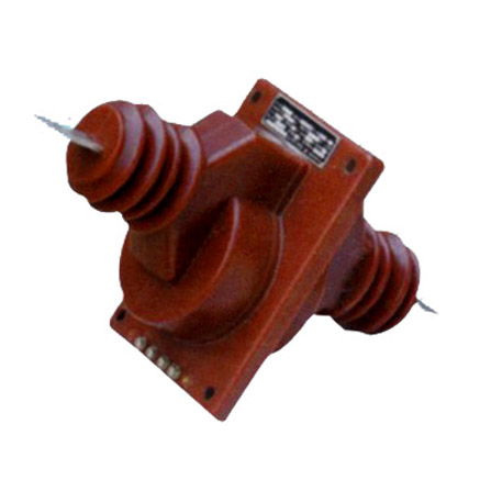
For Substation Metering & Protection: LA-10Q 11kV Cast-Resin Current Transformer per IEC 61869-2
Introduction to the LA-10Q Current Transformer
The LA-10Q is a high-voltage, cast-resin insulated current transformer (CT) engineered for accurate current measurement and robust protective relay coordination in 11kV (IEC-rated) medium-voltage power systems—equivalent to the domestic 10kV nominal voltage used in legacy Chinese distribution networks. Designed in strict compliance with IEC 61869-2 and GB/T 20840.2, this instrument transformer leverages vacuum pressure impregnation (VPI) epoxy resin technology to deliver superior dielectric strength, environmental resilience, and long-term operational stability without the fire or leakage hazards associated with oil-filled alternatives.
Operating Principle of Cast-Resin Insulation
Cast-resin insulation in the LA-10Q utilizes a thermosetting epoxy compound that fully encapsulates the primary conductor, secondary windings, and magnetic core under vacuum conditions. This VPI process eliminates air voids and moisture ingress pathways, resulting in a homogeneous dielectric structure with a relative permittivity (εr) of approximately 3.8–4.2 and volume resistivity exceeding 1×10¹⁴ Ω·cm at 20°C. The resin matrix provides mechanical support while maintaining thermal conductivity (~0.2 W/m·K) sufficient for dissipating heat generated during continuous operation or short-circuit events. Unlike oil-immersed CTs, which rely on liquid dielectric and require periodic oil sampling and tank integrity checks, the solid-state nature of cast-resin insulation ensures maintenance-free performance over decades, even in high-humidity or polluted environments (up to pollution degree IV per IEC 60664).
Advantages Over Oil-Immersed Designs
The LA-10Q’s cast-resin construction offers multiple engineering advantages critical for modern substations. First, it eliminates flammability risks—epoxy resin has a UL94 V-0 flame rating and does not produce combustible vapors. Second, its compact form factor reduces footprint by up to 30% compared to equivalent oil-filled units, enabling denser switchgear layouts. Third, the absence of seals, gaskets, or expansion tanks removes common failure points, enhancing reliability in seismic zones (tested to IEC 60068-2-6 for vibration resistance). Additionally, cast-resin CTs exhibit lower partial discharge levels (<5 pC at 1.2×Um/√3), ensuring signal fidelity for sensitive metering applications. These attributes make the LA-10Q particularly suitable for indoor GIS installations, urban substations, and renewable energy interconnection points where space, safety, and precision are paramount.
Typical Applications Overview
In practice, the LA-10Q serves dual roles: providing scaled-down secondary currents (typically 1A or 5A) for revenue-grade metering and delivering fault-current signals to protective relays such as overcurrent (50/51), earth-fault (50N/51N), and differential schemes. Its design accommodates both through-type and bar-type primary configurations, allowing direct integration onto 11kV busbars or cable terminations. Common deployment scenarios include ring main units (RMUs), pad-mounted transformers, and feeder breakers in utility distribution networks. With a standard thermal short-time withstand rating of 20 kA for 1 second (or 25 kA for 3 seconds upon request), the LA-10Q reliably survives downstream fault transients without saturation-induced measurement distortion—a critical requirement for selective coordination in meshed grids.
Technical Specifications
The LA-10Q is engineered to meet stringent electrical and environmental performance criteria defined by international and national standards. Below is a comprehensive specification table followed by detailed service condition parameters.
| Parameter | Value |
|---|---|
| Rated Voltage (Un) | 11 kV (IEC); 10 kV (domestic) |
| Maximum System Voltage (Um) | 12 kV |
| Primary Current (Ip) | 50 A to 3000 A (standard); custom up to 4000 A |
| Secondary Current (Is) | 1 A or 5 A |
| Current Ratio Tolerance | ±0.25% at rated current (for 0.2S/0.5S classes) |
| Accuracy Classes | Metering: 0.2S, 0.5S; Protection: 5P10, 5P20, 10P10 |
| Rated Burden (VA) | 2.5 VA to 30 VA (per IEC 61869-2 Table 102) |
| Insulation Level (LI/AC) | 75 kV / 28 kV (1.2/50 μs lightning impulse / 1-min power frequency) |
| Short-Time Thermal Current (Ith) | 20 kA for 1 s (standard); 25 kA for 3 s (optional) |
| Dynamic Withstand Current | 50 kA peak (2.5×Ith) |
| Ambient Temperature Range | –25°C to +40°C (storage: –40°C to +70°C) |
| Relative Humidity | Up to 95% non-condensing |
| Altitude Limit | ≤1000 m above sea level (derating required >1000 m) |
| Core Material | Grain-Oriented Electrical Steel (GOES), M4 grade, 0.27 mm thickness |
| Insulation System | VPI Epoxy Resin, Class F (155°C thermal index) |
Standard Service Conditions
The LA-10Q is rated for continuous operation under IEC 60038 standard service conditions. Ambient temperature must not exceed +40°C average over 24 hours, with a maximum of +45°C for brief periods. Relative humidity may reach 95% provided condensation does not occur on the housing surface—achieved via hydrophobic resin formulation and smooth external geometry that minimizes water retention. For installations above 1000 m altitude, the dielectric strength must be derated by 1% per 100 m increment due to reduced air density; thus, at 2000 m, the power frequency withstand voltage becomes 25.2 kV (28 kV × 0.9). The transformer is designed for three-phase systems with balanced loading; unbalanced conditions must not exceed 10% negative-sequence current to avoid core heating anomalies.
Accuracy and Burden Requirements
Accuracy class designation directly dictates permissible ratio and phase errors. For example, a 0.2S class LA-10Q must maintain ratio error ≤ ±0.2% and phase displacement ≤ ±10 minutes at 20–120% of rated current, with burden between 25–100% of rated VA. Protection-class units (e.g., 5P20) guarantee composite error ≤5% at 20× rated current into specified burden. It is critical that connected instrumentation (meters, relays) presents a burden within the CT’s rated VA range; exceeding this causes saturation and measurement collapse during faults. For instance, a 5A secondary CT rated at 15 VA cannot drive a 20 VA relay burden without accuracy degradation. Always verify total loop impedance (wiring + device) using Z = V/I, where V is the CT’s knee-point voltage derived from excitation curves.
Typical Applications
The LA-10Q’s versatility stems from its dual-certification (IEC and GB), robust insulation, and flexible ratio options, making it ideal across diverse power infrastructure segments.
Substation Secondary Metering
In 11kV primary substations, the LA-10Q supplies scaled current signals to revenue meters compliant with IEC 62053-22 (Class 0.2S). Installed on incomer and outgoing feeders, it enables precise energy billing and load profiling. For example, a 600/5A, 0.2S, 10 VA unit feeding a digital meter with 2.5 VA burden ensures error remains below ±0.15% across 5–120% load range. The cast-resin housing resists tracking from salt fog or industrial pollutants, critical for coastal or chemical plant substations. Its low phase error (<5 minutes at 100% In) also supports vector-based power quality analysis for harmonic distortion monitoring.
Industrial Power Distribution
Within manufacturing facilities operating on 10kV (domestic) systems, the LA-10Q integrates into motor control centers (MCCs) and transformer secondaries to provide inputs for multifunction protection relays (e.g., SEL-751). A typical 800/1A, 5P20 configuration delivers undistorted fault current during motor stall events (up to 6× full-load current), enabling reliable instantaneous overcurrent tripping. The solid insulation withstands frequent switching transients from variable-frequency drives (VFDs), while the GOES core minimizes hysteresis losses during cyclic loading—extending service life in 24/7 operations.
Renewable Energy Integration
Solar farms and wind parks connecting to 11kV distribution grids use the LA-10Q for both generation metering and anti-islanding protection. During cloud-induced irradiance fluctuations, the CT must accurately track rapid current changes without remanence-induced offset. The LA-10Q’s low coercivity GOES core (Hc ≤ 80 A/m) ensures minimal residual flux after fault clearance, preventing false tripping in directional earth-fault schemes. Units are often specified with dual cores—one 0.5S for revenue metering, another 10P10 for grid-code-compliant protection—housed in a single resin body to save space in compact inverter stations.
Rural and Suburban Distribution Networks
In remote areas with limited maintenance access, the LA-10Q’s hermetic seal and UV-stabilized resin housing ensure decades of trouble-free operation. Mounted on pole-top transformers or underground RMUs, it supports automated feeder reclosers requiring 5P10 accuracy for sectionalizing during tree-contact faults. The 11kV rating aligns with modern rural grid upgrades from legacy 6.6kV systems, while backward compatibility with 10kV switchgear simplifies retrofit projects. Its lightweight design (≈28 kg) facilitates manual handling during line crew deployments without crane assistance.
Compliance with International Standards
The LA-10Q’s design, testing, and certification strictly adhere to IEC 61869-2 (Instrument transformers – Part 2: Additional requirements for current transformers) and its Chinese counterpart, GB/T 20840.2. This dual compliance ensures global interoperability while meeting local regulatory mandates.
IEC 61869-2 Compliance Details
Under IEC 61869-2, the LA-10Q undergoes type tests including temperature rise (Clause 7.3), short-circuit withstand (Clause 7.4), and accuracy verification (Clause 7.6). The standard mandates that thermal stability be proven at 1.1× rated current for 8 hours, with winding temperature rise ≤60 K for resin-insulated CTs. Dielectric tests require 28 kV AC for 1 minute between primary and secondary/ground, with no flashover or disruptive discharge. Partial discharge inception voltage must exceed 1.2×Um/√3 (≈8.3 kV) with magnitude <10 pC. All production units receive routine tests per Clause 8: visual inspection, turns ratio check (±0.5% tolerance), and polarity confirmation.
GB/T 20840.2 Alignment and Key Differences
GB/T 20840.2 mirrors IEC 61869-2 but includes China-specific requirements. Notably, GB mandates a higher lightning impulse level (95 kV vs. IEC’s 75 kV) for 10kV systems, though the LA-10Q exceeds both by design. Additionally, GB requires mandatory third-party certification from CEPREI or CESI, including sample destruction tests for core lamination integrity. One key divergence is in accuracy class definitions: GB uses “0.2” instead of “0.2S,” but the LA-10Q meets the stricter S-class (extended range) criteria universally. This allows seamless export to Belt and Road Initiative projects while satisfying domestic State Grid procurement rules.
Testing and Certification Requirements
Certification involves three phases: type testing (once per design), routine testing (100% of units), and sample testing (per batch). Type tests are conducted at accredited labs like KEMA or TÜV, generating test reports valid for five years. Routine tests include insulation resistance (>1000 MΩ at 2500 V DC), ratio error (using calibrated standard CT), and polarity (via DC kick method). Each LA-10Q bears a permanent nameplate listing IEC/GB standards, serial number, and test voltages. Non-compliant units risk rejection during grid commissioning, particularly in EU or ASEAN markets enforcing CE marking under the Low Voltage Directive.
On-Site Testing Procedures
Post-installation verification ensures the LA-10Q performs within specifications before energization. All tests follow IEC 61869-2 Annex B and IEEE C57.13.2 guidelines.
Insulation Resistance Test
Using a 2500 V DC megohmmeter, measure resistance between primary conductor and secondary terminals/ground. Acceptance criterion: ≥1000 MΩ at 20°C. Correct for temperature using RT = R20 × 2(20–T)/10. Values below 500 MΩ indicate moisture ingress or resin cracking, requiring drying or replacement. Perform before and after dielectric tests to detect insulation degradation.
Turns Ratio Test
Apply low-voltage AC (5–10 V) to secondary winding and measure induced primary voltage. Calculate ratio as Vp/Vs; compare to nameplate. Tolerance: ±0.5% for protection class, ±0.25% for metering class. Alternatively, use a dedicated CT analyzer injecting 1–10% of rated current. Discrepancies >1% suggest turn-to-turn shorts or wiring errors.
Polarity Test
Verify reducing polarity (IEC standard): connect DC source (+) to P1, (–) to P2; momentary closure should cause positive deflection on a center-zero galvanometer connected to S1(+) and S2(–). Incorrect polarity reverses relay operating torque, causing miscoordination. Document results with timestamped oscillograms for audit trails.
Power Frequency Withstand Voltage Test
Apply 28 kV AC (RMS) at 50 Hz for 1 minute between primary and grounded secondary/housing. Use a calibrated HV test set with automatic trip at 10 mA leakage current. No flashover, smoke, or sustained arcing is permitted. Reduce voltage gradually post-test to avoid transient overvoltages. Conduct only after insulation resistance confirms dryness.
Short-Circuit Test (for CT)
Unlike VTs, CTs require short-circuit validation. Inject 10–20× rated current into primary (via portable test set) with secondary shorted. Monitor secondary waveform for saturation—knee point should exceed 2× rated burden voltage. For a 5P20 CT, composite error must stay ≤5% at 20×In. Excessive distortion indicates core damage during shipping or incorrect burden.
Preventive Maintenance Guide
Although cast-resin CTs are largely maintenance-free, periodic checks prevent latent failures in critical infrastructure.
Periodic Inspection Protocol
Annual visual inspections should verify: (1) housing integrity—no cracks, UV discoloration, or tracking marks; (2) terminal tightness—torque to 12 N·m for M6 studs; (3) grounding continuity—resistance <0.1 Ω between housing and substation grid. Clean surfaces with isopropyl alcohol if salt or dust accumulation exceeds 1 mg/cm². Infrared thermography during peak load can detect abnormal heating (>10 K above ambient) indicating internal faults.
Maintenance Intervals and Fault Diagnosis
Every five years, perform electrical retesting: insulation resistance, ratio, and polarity. Replace units showing >20% decline in insulation resistance or ratio error exceeding twice initial values. Common failure modes include: (a) secondary open-circuit during operation—causes core saturation and dangerous overvoltages (>3 kV); (b) moisture ingress at terminal seals—evidenced by fogging inside viewing windows; (c) mechanical stress from busbar expansion—leads to microcracks. Always de-energize and ground before handling. Maintain logs per ISO 55000 asset management standards.
| Interval | Action |
|---|---|
| Annually | Visual inspection, IR scan, terminal check |
| 5 Years | Full electrical retest (insulation, ratio, polarity) |
| 10 Years | Dielectric withstand retest (optional, if environment harsh) |
| After Fault | Mandatory ratio and insulation test before reuse |
Conclusion
The LA-10Q 11kV cast-resin current transformer represents a benchmark in medium-voltage instrumentation, combining IEC 61869-2 and GB/T 20840.2 compliance with field-proven reliability. Its vacuum-pressure-impregnated epoxy resin insulation eliminates fire hazards and maintenance burdens inherent in oil-filled designs, while the grain-oriented electrical steel core ensures metrological precision across metering (0.2S/0.5S) and protection (5P/10P) applications. With a rated short-circuit withstand of 20 kA/1s and dielectric strength validated to 75 kV LI/28 kV AC, the LA-10Q operates safely under extreme fault conditions without signal distortion. Designed for ambient temperatures from –25°C to +40°C and altitudes up to 1000 m, it adapts seamlessly to urban substations, industrial plants, renewable interconnects, and rural distribution networks. Rigorous on-site testing protocols—covering insulation resistance, ratio accuracy, polarity, and short-circuit response—guarantee performance integrity post-installation. Coupled with a preventive maintenance regimen spanning annual visual checks to quinquennial electrical retests, the LA-10Q delivers an expected service life of 25–30 years, significantly reducing lifecycle costs while supporting grid modernization initiatives worldwide. Its dual-voltage labeling (11kV IEC / 10kV domestic) further enhances versatility in global supply chains, making it a strategic choice for utilities and industrial operators prioritizing safety, accuracy, and longevity.